Method for reducing CO2 emission and producing microalgae lipid by using microalgae

A technology for the production of microalgae and CO2, applied in the direction of fat production, separation methods, fat oil/fat production, etc., can solve the problems of pollution in the microalgae culture system, achieve the effects of reducing pollution rate, increasing contact area, and increasing biomass

Inactive Publication Date: 2012-05-09
曹曦跃
View PDF0 Cites 22 Cited by
  • Summary
  • Abstract
  • Description
  • Claims
  • Application Information

AI Technical Summary

Problems solved by technology

[0004] The object of the present invention is to provide a method to reduce CO by using microalgae 2 Discharge method for pro...

Method used


Image

  • Method for reducing CO2 emission and producing microalgae lipid by using microalgae
  • Method for reducing CO2 emission and producing microalgae lipid by using microalgae
  • Method for reducing CO2 emission and producing microalgae lipid by using microalgae

Examples


Embodiment 1

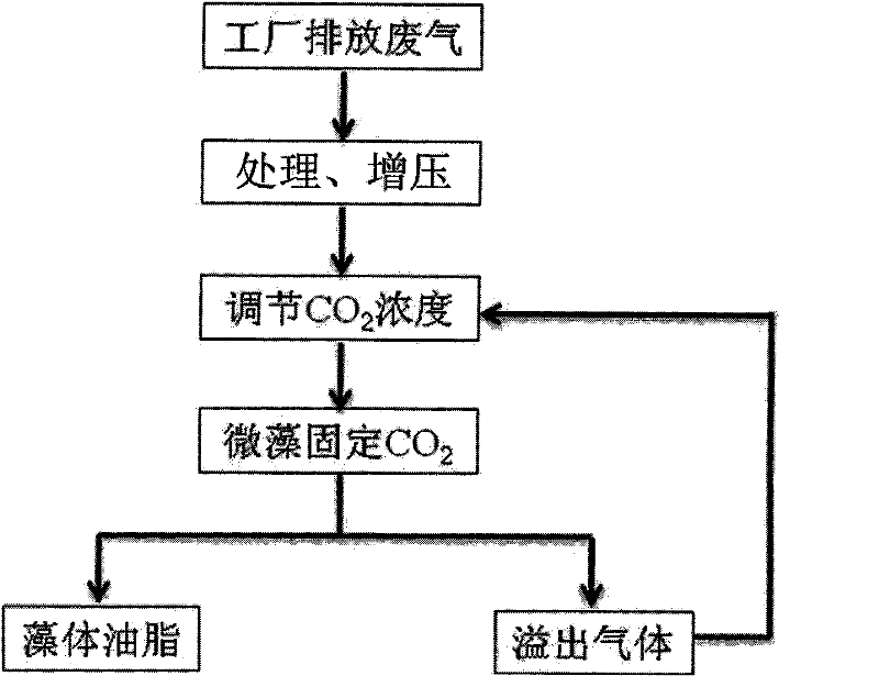
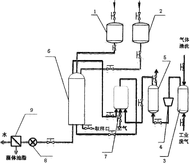
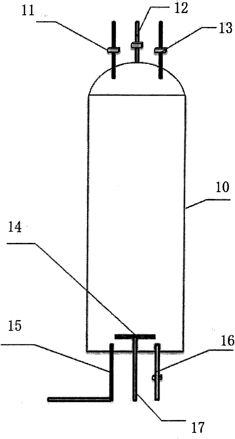
[0028] Use of microalgae to reduce CO as described in this example 2 The method for discharging and producing microalgae oil, its technological process is as follows figure 1 As shown, the treatment and pressurization of exhaust gas from the factory, and the adjustment of CO in exhaust gas 2 content and CO fixation by microalgae 2 . equipment used such as figure 2 As shown, it consists of seed tank 1, medium storage tank 2, scrubber 3, air compressor 4, cooler 5, sealed photobioreactor 6, gas filter regulator 7, flow meter 8 and algae separator 9 composition. The structure of the sealed photobioreactor 6 is as follows: image 3 , Figure 4 As shown, comprising cylinder 10, described cylinder 10 is transparent cylinder, and its top wall is provided with air outlet 11, inoculation port 12 and feeding port 13, and its bottom wall is provided with liquid outlet 15, sampling port 15 and The air inlet 17 is provided with a microbubble generator 14 at the bottom thereof.

Embodiment 2

[0030] In this example, Dunaliella salina is used as algae species to treat industrial waste gas from power plants, and the equipment described in Example 1 is used.

[0031] Dunaliella salina medium formula:

[0032] Liquid A: NaCl 5-10g

[0033] FeC 6 h 5 o 7 0.001g

[0034] Seawater 500ml

[0035] Sea mud extract 20-30ml

[0036] Liquid B: NaNO 3 0.5g

[0037] K 2 HPO 4 0.05g

[0038] Seawater 500ml

[0039] When in use, the volume ratio of medium A and medium B is 1:1, and the medium composed of Dunaliella salina seed liquid A and medium B is mixed. If you add 2-3‰ of urine, the effect will be better. The volume ratio of the seed liquid to the medium is 1:4-1:9 and inoculated in the photobioreactor, the liquid filling volume is 90%, and the density of the inoculation algae is controlled at 2×10 5 cells / ml, the best inoculation time is between 8 and 10 in the morning. CO emissions from plants for dedusting, press...

Embodiment 3

[0042] In this embodiment, chlorella is used as an algal species to treat industrial waste gas from a power plant, and the equipment described in Embodiment 1 is used.

[0043] Chlorella commonly used medium formula:

[0044] NH 4 NO 3 50-100μg

[0045] K 2 HPO 4 5μg

[0046] FeC 6 h 5 o 7 0.1-0.5mg

[0047] Seawater 1000ml

[0048] When in use, the ratio of the seed liquid to the culture medium is 1: 4, and it is inoculated in the sealed photobioreactor 6, and the liquid filling volume is 90%, and the density of the inoculated algae is controlled at 2 × 10 5 cells / ml, the best inoculation time is between 8 and 10 in the morning. CO emissions from plants for dedusting, pressurization and conditioning 2 , pass into the sealed photobioreactor 6 with 800ml / min through microbubble generator 14, make CO 2 The gas is in full contact with the algae species, and the agitation of the culture solution is realized to avoid aggregation and adhering to the wall...


PUM


Abstract

The invention relates to a method for reducing CO2 emission and producing microalgae lipid by using microalgae. The method comprises the following processing steps of: (1) treating and pressurizing exhaust gas emitted from a factory, removing liquid drops and particles from the CO2-containing exhaust gas emitted from the factory, and pressurizing the CO2-containing exhaust gas to 0.1-2.5 Mpa; (2) adjusting the content of CO2 in the exhaust gas, and adjusting the exhaust gas treated and pressurized in the step (1) so that the volume concentration of CO2 contained in the exhaust gas reaches 10-25%; and (3) fixing CO2 by using microalgae, injecting a microalgae culture medium into a sealed bioreactor, adding microalgae spices in the logarithmic phase into the sealed bioreactor with the inoculation quantity of 5%-20%, introducing the exhaust gas the CO2 concentration of which is adjusted in the step (2) into the sealed bioreactor with the flow rate of 500-1000 ml/min under stirring, and culturing microalgae at a temperature suitable for microalgae growth to fix CO2.

Description

technical field [0001] The invention belongs to biological carbon dioxide fixation method, in particular to a method for CO2 fixation with microalgae 2 Fix, reduce CO 2 Method for releasing and producing microalgal lipid. Background technique [0002] Excessive combustion of coal, oil and natural gas in modern industrial society releases a large amount of CO 2 gas, CO 2 The gas has the functions of heat absorption and heat insulation. The result of its increase in the atmosphere is an invisible glass cover, which prevents the heat radiated by the sun from the earth from radiating to the outer space, resulting in the heating of the earth's surface. Therefore, CO 2 Also known as greenhouse gas. Industry continues to emit CO 2 Has seriously affected the earth's climate and environment, reducing CO in the atmosphere 2 It has become a major problem that governments and enterprises must face. [0003] Under the current technical conditions, the biological carbon dioxide fi...

Claims


Application Information

Patent Timeline
IPC IPC(8): B01D53/84B01D53/62C11B1/00
CPCY02A50/20
Inventor 曹曦跃乔代蓉徐辉
Owner 曹曦跃
Why Eureka
Try Eureka