
Method for producing clean diesel from coal tar

A coal tar, clean technology, applied in the petroleum industry, hydrocarbon oil treatment, hydrotreating process, etc., can solve the problems of low cetane number of diesel fraction, low catalyst utilization rate, short operation cycle, etc., and achieve excellent product properties , to avoid catalyst deactivation, to expand the effect of the range

Active Publication Date: 2012-05-09
CHINA PETROLEUM & CHEM CORP +1
View PDF12 Cites 17 Cited by
  • Summary
  • Abstract
  • Description
  • Claims
  • Application Information

AI Technical Summary

Problems solved by technology

[0012] The purpose of the present invention is to provide a method for producing clean diesel oil from coal tar, specifically, to solve the problem of low cetane number of diesel oil cuts obtained after hydrogenation of coal tar obtained in the prior art, low catalyst utilization rate, and device operation short cycle problem

Method used


Image

  • Method for producing clean diesel from coal tar
  • Method for producing clean diesel from coal tar
  • Method for producing clean diesel from coal tar

Examples


Embodiment 1

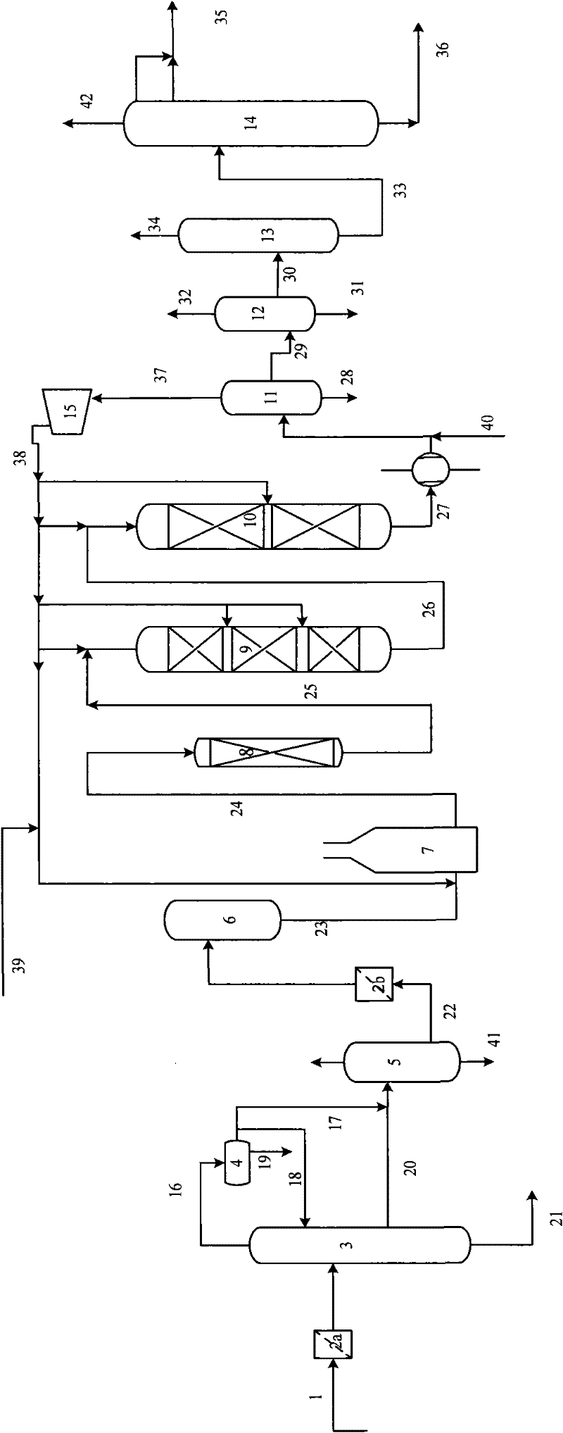
[0040] Hydrogenation protection reactor: The filling height of BN-01 bird's nest type inert protection material is 500mm, and the filling volume ratio of RGC-10A protection agent, RGC-10B protection agent and RGC-1 protection agent is 2:1.5:1.

[0041] Hydrofinishing reactor I and hydrofinishing reactor II are divided into 6 catalyst beds, and the catalyst loading ratio of each bed is 0.9:1.1:2.2:3.3:4.4:5.5:6.5.

[0042] The pre-fractionation unit adopts relatively harsh operating conditions, and the coal tar light fraction A obtained by fractionation has high aromatics and impurity content, so the above-mentioned catalyst loading ratio is used for design.

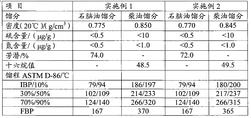
[0043] The density of coal tar light fraction A is 0.9500g / cm 3 , the sulfur content is 3700μg / g, the nitrogen content is 5400μg / g, under the operating conditions shown in Table 3, the density of 0.850g / cm can be produced 3 Clean diesel oil with a sulfur content of less than 10 μg / g, a nitrogen content of less than 1.0 μ...

Embodiment 2

[0045] Hydrogenation protection reactor: The filling height of BN-01 bird's nest type inert protection material is 200mm, and the filling volume ratio of RGC-10A, RGC-10B and RGC-1 protection agent is 1:1:1.

[0046] The hydrofinishing reactor I and the hydrofinishing reactor II are divided into five catalyst beds, and the catalyst loading ratio of each bed is 1:2:3:4:5.

[0047] The pre-fractionation unit adopts relatively mild operating conditions, and the coal tar light fraction B aromatics and impurities obtained by fractionation are slightly lower, and the above-mentioned catalyst loading ratio is used for design.

[0048] The density of coal tar light fraction B is 0.9398g / cm 3 , the sulfur content is 3400μg / g, the nitrogen content is 5000μg / g, under the operating conditions shown in Table 3, the density of 0.845g / cm can be produced 3 Clean diesel oil with a sulfur content of less than 10 μg / g, a nitrogen content of less than 1.0 μg / g, and a cetane number of 49.5. At t...


PUM

PropertyMeasurementUnit
Densityaaaaaaaaaa
Densityaaaaaaaaaa

Abstract

A method for producing clean diesel from coal tar comprises the following steps: introducing the coal tar raw materials and hydrogen into two tandem hydrogenation reaction zones in turn under the hydrogenation reaction to contact with a plurality of catalyst beds in the hydrogenation reaction zones; filling hydrogenation protective agent in the first hydrogenation reaction zone, and filling hydrorefining catalyst in the second hydrogenation reaction zone; controlling the temperature rise of each catalyst bed of hydrorefining reaction zone as 15-35 DEG C. After adopting the method provided by the invention, the sulphur content of the diesel product is less than 50 mug / g and the cetane number of the diesel product is more than 45. The method also can be used for transforming the gasoline fraction in the coal tar into reforming feedstock with more than 70% of potential aromatics. The invention can be also used for effectively increasing the use ratio of catalyst to improve the chemical reaction effect and prolong operating period of device.

Description

technical field [0001] The invention relates to a method for refining coal tar in the presence of hydrogen, more specifically, a method for hydrogenating coal tar to produce clean diesel oil. Background technique [0002] With the continuous and high-speed development of social economy, my country's demand for petroleum products is also increasing. However, petroleum is a non-renewable energy source and is facing a crisis of depletion. In contrast, China has relatively abundant coal reserves, so producing liquid fuel from coal has become a basic direction of coal processing and utilization. [0003] On the other hand, with the rapid growth of the international and domestic steel industry, the coking industry is showing a high growth trend. Therefore, the output of coal tar is increasing, and the clean processing and effective utilization of coal tar are becoming more and more important. At present, the conventional processing method is to cut various fractions with concent...

Claims


Application Information

Patent Timeline
IPC IPC(8): C10G65/02C10G67/02
Inventor 张毓莹胡志海李猛陈水银刘清河聂红
Owner CHINA PETROLEUM & CHEM CORP
Learn More