Vacuum brazing method for high-temperature alloy pipe parts
A technology of high temperature alloy and brazing method, applied in the field of parts processing, can solve the problems of blurred black lines in X-ray film, difficulty in ensuring brazing gap and uniformity, etc.
Active Publication Date: 2012-06-20
AECC AVIATION POWER CO LTD
View PDF5 Cites 17 Cited by
- Summary
- Abstract
- Description
- Claims
- Application Information
AI Technical Summary
Problems solved by technology
Since the vacuum brazing process has strict requirements on the fit gap of the welded joints, and it is difficult to ensure the uniform brazing gap of the whole circle of pipe parts during the assembly process, the welding quality inside the brazing seam after welding adopts the X-ray inspection method, X-ray film There is a fuzzy "black line" problem on the surface, which makes it difficult to give an accurate judgment on the welding quality of the parts
Method used
View moreImage
Smart ImageViewing Examples
Examples
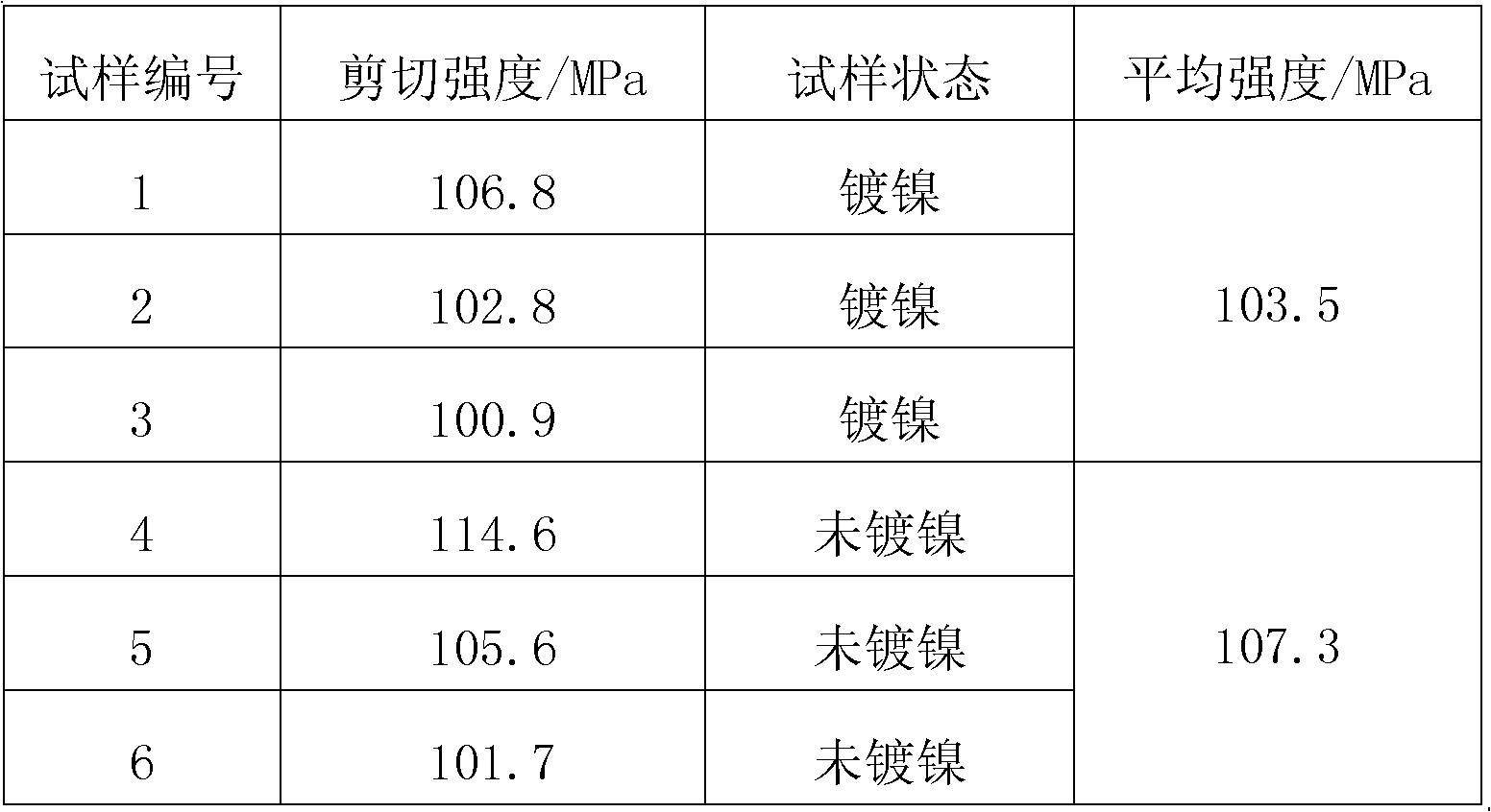
Embodiment
[0016] Step 1: Plating nickel on the welding part of the superalloy pipe parts to be brazed.
Login to View More PUM
| Property | Measurement | Unit |
|---|---|---|
| thickness | aaaaa | aaaaa |
Abstract
The invention provides a vacuum brazing method for high-temperature alloy pipe parts. The method comprises the following steps: firstly coating nickel in the welding positions of pipe parts, secondly assembling high-temperature alloy pipe parts to be brazed in a way that the assembly gap is within the range of 0.03 mm to 0.08 mm, thirdly presetting an amorphous foil-like brazing alloy sheet with the thickness of 0.03 mm in the assembly gap of the high-temperature alloy pipe parts to be brazed, subsequently positioning the high-temperature alloy pipe parts by argon arc welding, and finally coating and injecting a solder paste made of powdery brazing alloy at the joint of the pipe parts and loading the high-temperature alloy pipe parts into a vacuum brazing furnace for vacuum brazing. The amorphous brazing alloy foil is preset in the assembly gap of the pipe parts to ensure welding and assembly gap. The amorphous brazing alloy foil and the powdery brazing alloy interact during the welding process, so as to facilitate spread and moistening of the brazing alloy and also reduce the flow distance of the powdery brazing alloy, thus obtaining a great improvement of welding quality.
Description
technical field [0001] The invention relates to the field of parts processing, in particular to a vacuum brazing method for high-temperature alloy pipe parts. Background technique [0002] In the manufacture and assembly of superalloy pipe parts of aero-engines in my country, the vacuum brazing process is often used. Since the vacuum brazing process has strict requirements on the fit gap of the welded joints, and it is difficult to ensure the uniform brazing gap of the whole circle of pipe parts during the assembly process, the welding quality inside the brazing seam after welding adopts the X-ray inspection method, X-ray film There is a fuzzy "black line" problem on the surface, and it is difficult to give an accurate judgment on the welding quality of the parts. For a long time, the vacuum brazing quality of superalloy pipe parts has restricted the normal delivery of engines. Contents of the invention [0003] technical problem to be solved [0004] In order to solve ...
Claims
Login to View More Application Information
Patent Timeline
 Patent Type & Authority Applications(China)
IPC IPC(8): B23K1/008B23K1/20
Inventor 张军康文军杨磊时孝雷王炜张建伟
Owner AECC AVIATION POWER CO LTD
Features
- R&D
- Intellectual Property
- Life Sciences
- Materials
- Tech Scout
- Unparalleled Data Quality
- Higher Quality Content
- 60% Fewer Hallucinations
Learn More Browse by: Latest US Patents, China's latest patents, Technical Efficacy Thesaurus, Application Domain, Technology Topic, Popular Technical Reports.
© 2025 PatSnap. All rights reserved.Legal|Privacy policy|Modern Slavery Act Transparency Statement|Sitemap|About US| Contact US: help@patsnap.com

