
Lonky detection method of aspheric surface with heavy calibre

A detection method and an aspheric surface technology, applied to measuring devices, instruments, optical devices, etc., can solve the problems of low measurement efficiency, inaccessibility, and measurement result errors, and achieve simple detection structure, convenient and fast operation, and anti-aliasing shape effect

Inactive Publication Date: 2012-06-20
SICHUAN UNIV
View PDF2 Cites 15 Cited by
  • Summary
  • Abstract
  • Description
  • Claims
  • Application Information

AI Technical Summary

Problems solved by technology

The three-coordinate measuring instrument is a detection instrument in the surface profile method. It uses the measuring head to directly act on the surface of the aspheric mirror to directly measure the three-dimensional coordinates of each point on the surface of the aspheric mirror. This measurement method has high precision, but the measurement The head is easy to damage the surface of the mirror under test, the measurement efficiency is low, and the measurement caliber is also limited
However, the traditional zero-Ronchi detection method has some defects. 1) It cannot provide enough measurement data, mainly because the information of the area between the fringes cannot be obtained; 2) the moiré fringe pattern formed by the coaxial detection will be It brings errors to the measurement results; 3) The edge of each band on the traditional compensation grating has a jagged shape; 4) When testing different mirror surfaces, the corresponding compensation grating must be specially made, which brings inconvenience to the actual detection

Method used


Image

  • Lonky detection method of aspheric surface with heavy calibre
  • Lonky detection method of aspheric surface with heavy calibre
  • Lonky detection method of aspheric surface with heavy calibre

Examples


Embodiment Construction

[0021] The present invention will be further described in detail below in conjunction with the accompanying drawings, working principles and embodiments.

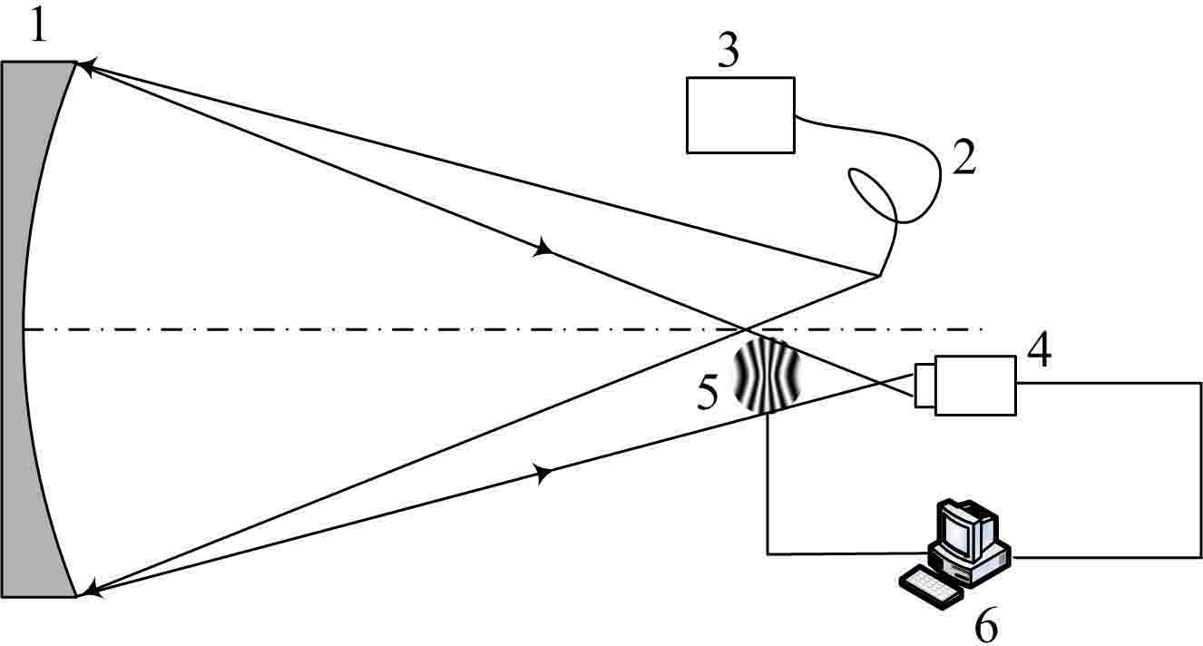
[0022] figure 1 Is the schematic diagram of the detection device, where 1 is the mirror to be tested, 2 is the optical fiber, 3 is the optical fiber lighting source, 4 is the CCD camera, 5 is the transmission liquid crystal display screen, and 6 is the computer. During detection, a compensated sinusoidal grating needs to be displayed on the transmission liquid crystal display 5 .

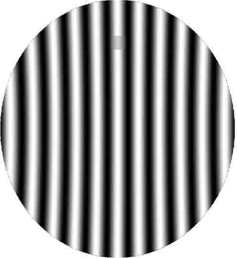
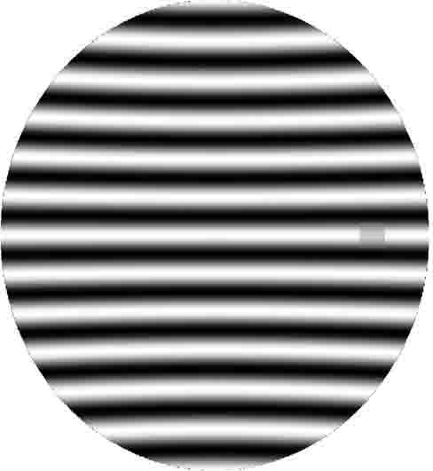
[0023] Compensated sinusoidal gratings are designed as figure 2 As shown, when designing a compensated sinusoidal grating, it is assumed that there are given straight sinusoidal fringes on the ideal surface, and the curved fringes on the compensated grating are calculated using ray tracing and the phase information of the fringes. exist figure 2 center of ideal face shape o A Cartesian coordinate system is established for the coordinate or...


PUM


Abstract

The invention relates to a lonky detection method of an aspheric surface with a heavy calibre. A compensating sinusoidal grating is designed by using phase information of a ray trace and a sine fringe and displayed on a transmissive type liquid crystal display screen; the transmissive type liquid crystal display screen is also a phase shifter so that the compensating sinusoidal grating displayed on the transmissive type liquid crystal display screen generates phase shift. Light emitted from an off-axis point light source passes through the compensating grating after being reflected by a mirror surface. A video camera records a phase-shift fringe pattern carrying deviation information of the mirror surface relative to an ideal face shape of the mirror surface. Actual lateral aberration and corresponding ideal lateral aberration of the tested mirror surface can be determined by analyzing the phase-shift fringe pattern, the deviation gradient of the tested mirror surface can be obtained on the basis of a geometrical principle of the lonky detection and the deviation of the tested mirror surface is obtained by integration of the tested mirror surface so that a three-dimensional surface shape of the tested mirror surface is rebuilt. According to the invention, it is unnecessary to manufacture a special compensating grating as to each type of aspherical mirror. The lonky detection method has the advantages of flexibility, convenience and high detection accuracy, and has an important application prospect in detection of the aspheric surface with the heavy calibre.

Description

technical field [0001] The invention relates to an optical detection technology, in particular to the detection of a rotationally symmetrical large-diameter aspheric mirror in the stages of fine grinding and initial polishing, and belongs to the field of advanced optical manufacturing and detection technology. Background technique [0002] Aspherical mirrors have the advantages of increasing the freedom of optical design, simplifying system structure, reducing weight, and improving the image quality of optical systems. With the development of advanced optical manufacturing technology and the improvement of imaging quality requirements, aspheric mirrors are widely used in space communication, celestial observation, military and civilian industries. However, compared with spherical mirrors, the manufacture of aspherical mirrors is much more difficult, which puts forward higher requirements for its processing and inspection technology. [0003] At present, the detection techni...

Claims


Application Information

Patent Timeline
IPC IPC(8): G01B11/25
Inventor 苏显渝郭春凤陈文静张启灿向立群曹益平刘元坤
Owner SICHUAN UNIV
Learn More