Flow battery diaphragm and its preparation method

A liquid flow battery and diaphragm technology, which is applied in the direction of fuel cells, battery pack components, fuel cell components, etc., can solve the problems of attenuation of vanadium resistance and increase of internal resistance of batteries, etc., and achieve reduced membrane resistance and long working life , Reduce the permeability and the effect of water molecule migration number

Active Publication Date: 2012-06-27
SHANDONG DONGYUE WEILAI HYDROGEN ENERGY MATERIAL CO LTD
View PDF3 Cites 6 Cited by
  • Summary
  • Abstract
  • Description
  • Claims
  • Application Information

AI Technical Summary

Problems solved by technology

However, the metal salts filled in the micropores will also repel the hydrogen ions transferred at the positive and negative electrodes during charging and discharging of the vanadium battery, increasing the internal resistance of the battery.
In addition, since the two-electrode electrolyte of the vanadium battery and the hydrogen ions transferred between the two stages are strongly acidic, the metal salt will dissolve and electromigrate over time, so the vanadium resistance of the membrane will continue to decay over time.

Method used


Image

  • Flow battery diaphragm and its preparation method
  • Flow battery diaphragm and its preparation method
  • Flow battery diaphragm and its preparation method

Examples


Embodiment 1

[0049] The tetrafluoroethylene with the exchange capacity of 1.35mmol / g and the monomer of formula (V) are copolymerized into perfluorosulfonic acid resin, and its molecular repeating structure is as follows:

[0050]

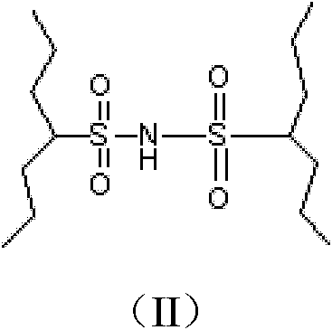
[0051] The above-mentioned perfluorosulfonic acid resin was extruded through an extruder at 210° C. to extrude a film with a thickness of 50 μm. The above-mentioned extruded film was soaked in 20 wt% ammonia water for 1 min. After taking it out, place it at 250°C for heat treatment to generate cross-linked structures (II) on both sides of the film. Put the crosslinked membrane in 10wt% sodium hydroxide for 80°C hydrolysis for 8 hours, then place it in 5wt% sulfuric acid, keep the temperature at 80°C for 3 hours, wash until neutral, and obtain a crosslinked flow battery diaphragm.

Embodiment 2

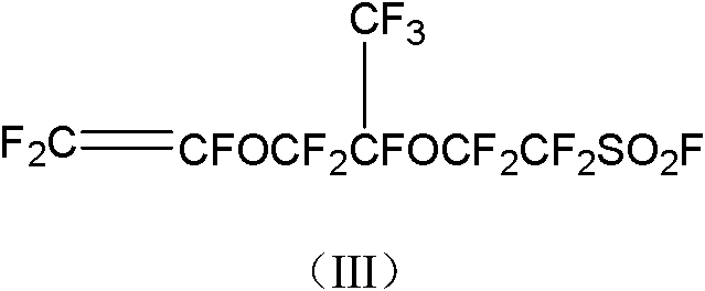
[0053] The tetrafluoroethylene with the exchange capacity of 1.00mmol / g and the monomer of formula (III) are copolymerized into perfluorosulfonic acid resin, and its molecular repeating structure is as follows:

[0054]

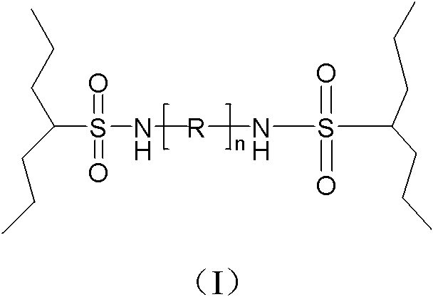
[0055] Through an extruder, extrude at 250° C., and the extruded thickness is 100 μm. One side of the extruded film was placed in 10 wt% hydrazine solution for 10 min. After taking it out, place the film at 230° C. for 3 hours for heat crosslinking to form a film with a crosslinked structure of n=0 in formula (I). The cross-linked membrane was hydrolyzed in 10% sodium hydroxide at 80° C. for 8 hours to obtain a cross-linked flow battery separator.

Embodiment 3

[0057] The exchange capacity is 1.20mmol / g tetrafluoroethylene and the monomer of formula (III) and the monomer of formula (VI) terpolymerized into perfluorosulfonic acid resin

[0058] Through an extruder, extrude at 190° C., and the extruded thickness is 150 μm. The above extruded film was immersed in 10wt% perfluoromethylenediamine of formula (VII)x=2 for 20min. After taking it out, place the film at 200° C. for thermal crosslinking for 3 hours to form a crosslinked structure with n=2 in formula (I) on both sides of the film. The cross-linked membrane was hydrolyzed in 10% sodium hydroxide at 80° C. for 8 hours to obtain a cross-linked flow battery separator.


PUM

PropertyMeasurementUnit
thicknessaaaaaaaaaa

Abstract

The invention relates to a flow battery diaphragm and its preparation method. The flow battery diaphragm is a film formed by a perfluorinated sulfonic acid resin and at least one surface of the film reacts with a cross-linking agent to form a chemical bonding cross-linking network structure. Due to the existence of the surface cross-linking structure, vanadium ion permeability and water mobility of the film are greatly reduced in comparison with that of a traditional film. At the meantime, as the perfluorinated sulfonic acid resin is used as the film-forming resin, the diaphragm in a battery is endowed with excellent chemical stability and long service life. The invention also provides a preparation method of the flow battery diaphragm.

Description

technical field [0001] The invention belongs to the field of functional polymer composite materials, in particular to a liquid flow battery diaphragm with a surface cross-linked network structure and a preparation method thereof. Background technique [0002] The all-vanadium redox flow battery uses vanadium ions in different valence states as the working medium of the positive and negative electrodes to achieve the purpose of energy storage. Since the positive and negative electrodes use the same element, there will be no cross-contamination of metal ions. Compared with other batteries, this kind of flow battery has the advantages of low cost and large energy storage capacity. It is especially suitable for the storage of unstable power in the process of renewable energy generation such as solar power generation and wind power generation and the "cutting wind and filling the valley" of the power grid. It has a very broad application space in the future new energy market. ...

Claims


Application Information

Patent Timeline
Patent Type & Authority Applications(China)
IPC IPC(8): H01M8/02H01M2/16C08J7/06C08L27/18C08L29/10H01M8/0221
CPCY02E60/12Y02E60/50
Inventor 唐军柯杨玉清申玉鹏庞桂花
Owner SHANDONG DONGYUE WEILAI HYDROGEN ENERGY MATERIAL CO LTD
Why Eureka
Try Eureka