
Diamond-coated cutting tool

A cutting tool and diamond technology, applied in the field of diamond-coated cutting tools, can solve the problem of insufficient wear resistance on the surface of diamond film, and achieve the effects of improving chip discharge, seeking long life and excellent wear resistance.

Inactive Publication Date: 2012-07-11
MITSUBISHI MATERIALS CORP
View PDF9 Cites 4 Cited by
  • Summary
  • Abstract
  • Description
  • Claims
  • Application Information

AI Technical Summary

Problems solved by technology

[0009] In the above-mentioned conventional diamond-coated tools, the diamond is composed of a laminated structure, so it exhibits excellent strength, toughness, and finishing surface accuracy in continuous cutting or interrupted cutting of Al alloys with a small Si content. When machining difficult-to-cut materials such as CFRP with higher specific strength and specific rigidity than metal materials, Al alloys with high Si content and graphite with high weldability, the wear resistance of the diamond film surface is not sufficient. Reach service life in a relatively short time

Method used


Image

  • Diamond-coated cutting tool
  • Diamond-coated cutting tool
  • Diamond-coated cutting tool

Examples


Embodiment

[0052] First, prepare the raw material powders shown in Table 1, which all have a predetermined average particle size in the range of 1 to 3 μm, and prepare mixed powders with the same composition shown in Table 1, wet-mix this with a ball mill for 72 hours, and dry it. , Formed by 100MPa pressure stamping to form round rod compacts with diameters of 10mm and 8mm, and sinter these round rod compacts to manufacture sintered bodies. In addition, use grinding to process the outer diameter of the groove forming part to 8mm and 6mm. At this time, the outer peripheral edge and the edge of the cutting edge are subjected to gas blasting using SiC abrasive grains of #600 and finishing grinding of 30 μm or more using a diamond wheel of #1200 to produce the outer edge. Tool bases 1-5 with a diameter of 8 mm and tool bases 6-10 with an outer diameter of 6 mm.

[0053] (a) Next, on the above-mentioned tool substrates 1 to 10, use a solution of mixing sulfuric acid, hydrogen peroxide and wa...


PUM

PropertyMeasurementUnit
particle diameteraaaaaaaaaa
thicknessaaaaaaaaaa

Abstract

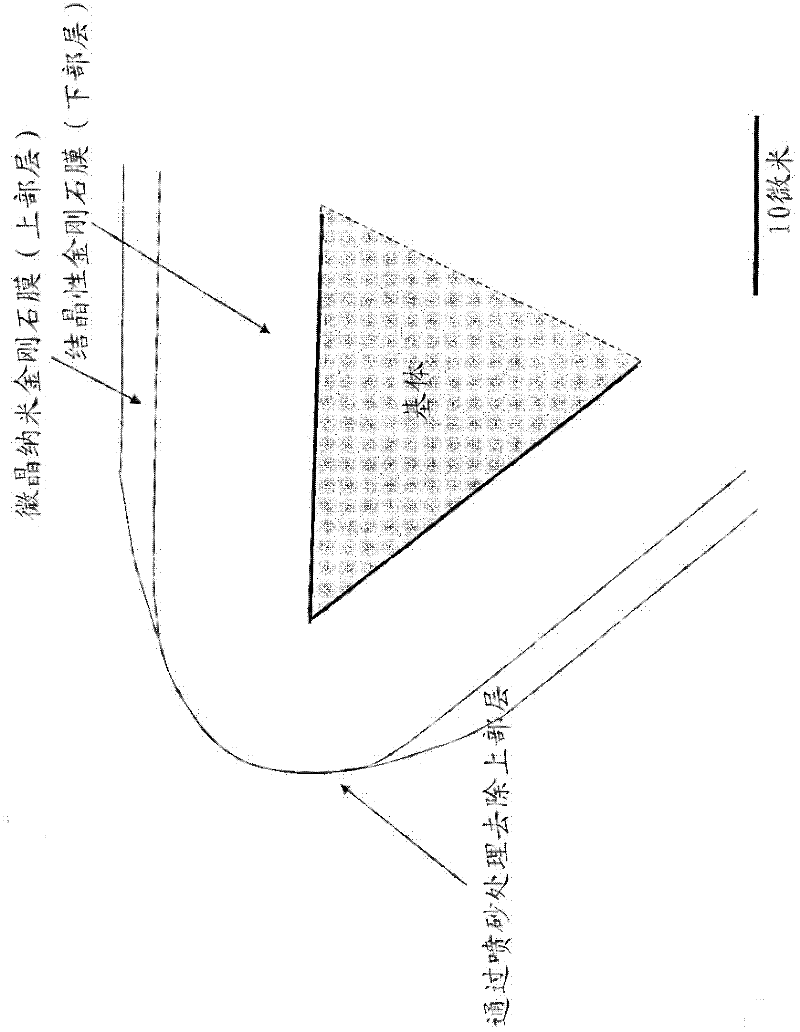
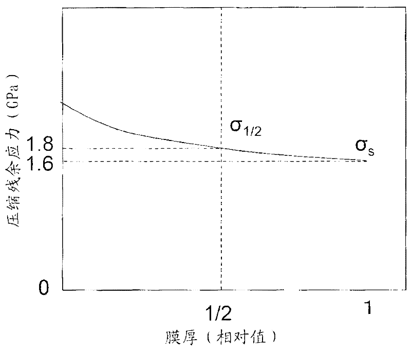
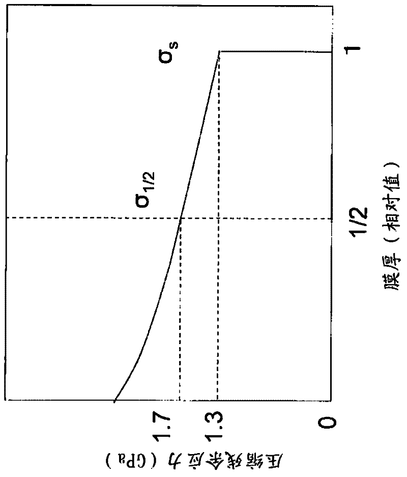
The present invention provides a diamond-coated cutting tool, which has an excellent wear resistance in the drilling machining and end mill machining process of materials hard to be cut like CFRP material, aluminium alloys containing high silicon, and graphites. In the diamond-coated cutting tool, the base body surface of the tool, formed by tungsten carbide-based hard alloy is coated with a crystallinity diamond film as a lower portion layer, and with a crystallite nanometer diamond film as an upper layer. Only the ridge portion of the cutter tip is processed through wet-type sandblasting to enable the lower layer to be exposed, wherein when the compressive residual stress formed on the lower layer of the ridge portion of the cutter tip of the tool is determined, the residual stress value sigma s of the exposed surface of the lower layer is 1.5-3 GPa; and when the residual stress value formed at the 1 / 2 position of the lower layer of the ridge portion of the cutter tip is set as sigma 1 / 2, the value of sigma s / sigma 1 / 2 is 0.8-1.0.

Description

technical field [0001] The present invention relates to a diamond coated cutting tool such as end mills and drills coated with a diamond film on the surface of a tool base (hereinafter referred to simply as a tool base) made of tungsten carbide (WC)-based cemented carbide. A diamond-coated cutting tool (hereinafter referred to as a diamond-coated cutting tool) that exhibits excellent wear resistance after long-term use in the cutting of difficult-to-cut materials such as carbon fiber reinforced composite materials (CFRP materials), high-Si aluminum alloys, and graphite. covering tools). Background technique [0002] Conventionally, there are known diamond-coated tools in which a diamond film is coated on the surface of a tool substrate, and it is known to use highly crystalline diamond and microcrystalline diamond (or amorphous diamond) in order to improve the strength and toughness of the film. The diamond film is composed of a laminated structure, and the diamond film is ...

Claims


Application Information

Patent Timeline
Patent Type & Authority Applications(China)
IPC IPC(8): B23B51/00B23C5/00B23B27/14C23C16/27C23C16/44
Inventor 高冈秀充长田晃高岛英彰
Owner MITSUBISHI MATERIALS CORP
Learn More