
Method for manufacturing ceramic filled polytetrafluoroethylene glass fiber copper-clad substrate

A technology of polytetrafluoroethylene and glass fiber, which is applied in the field of copper-clad substrate manufacturing with ceramic-filled polytetrafluoroethylene glass fiber, can solve the problems of affecting the use effect, low dielectric constant, insufficient strength, etc., and achieve improved peel strength , high thermal conductivity, and the effect of improving high electrical conductivity

Inactive Publication Date: 2012-07-11
珠海国能复合材料科技有限公司
View PDF2 Cites 24 Cited by
  • Summary
  • Abstract
  • Description
  • Claims
  • Application Information

AI Technical Summary

Problems solved by technology

[0003] At present, with the continuous advancement of electronic technology, electronic information products continue to develop in the direction of high frequency and high speed, and traditional substrate materials are gradually replaced by high-speed, high-reliability ceramic substrate materials. Copper substrates are used as conductive substrates for templates. Among them, polytetrafluoroethylene glass fiber has become a commonly used material due to its high temperature resistance of 250 ° C, low temperature resistance of -100 ° C, corrosion resistance, high lubrication, and excellent electrical properties. High dielectric constant and low loss, low pressure and low temperature in the lamination process can be widely used in high-frequency microwave circuits. However, in practical applications, the combination of ordinary substrates and copper foils will cause insufficient strength. In addition, PTFE glass fiber copper clad also has the disadvantages of low dielectric constant and large loss, which affects the use effect

Method used

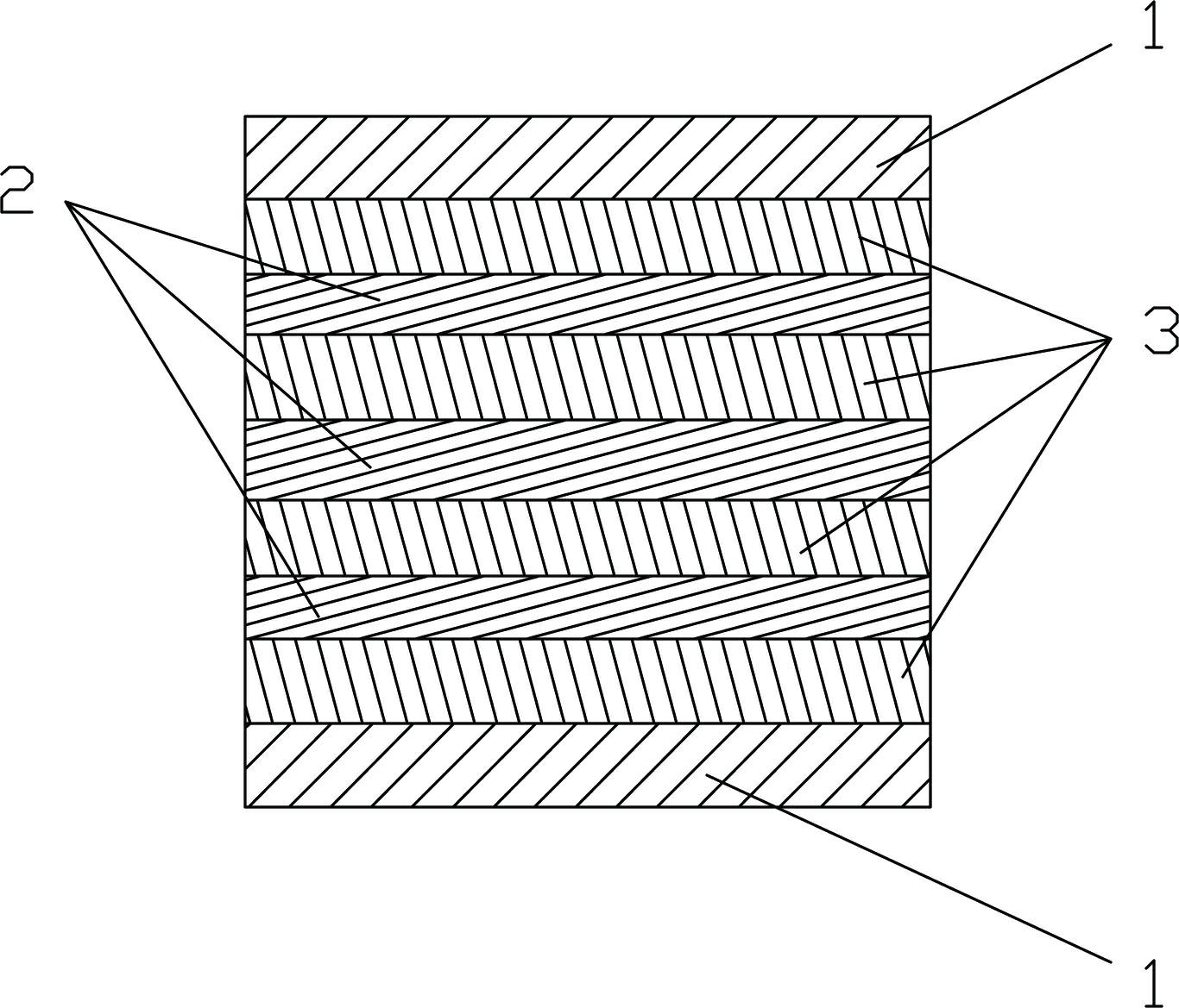
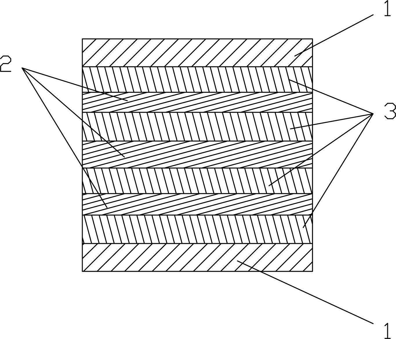
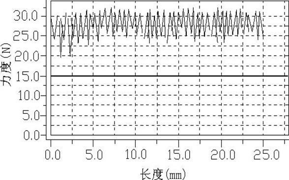

Image

  • Method for manufacturing ceramic filled polytetrafluoroethylene glass fiber copper-clad substrate
  • Method for manufacturing ceramic filled polytetrafluoroethylene glass fiber copper-clad substrate
  • Method for manufacturing ceramic filled polytetrafluoroethylene glass fiber copper-clad substrate

Examples


Embodiment Construction

[0017] refer to figure 1 . A method for manufacturing a ceramic-filled polytetrafluoroethylene glass fiber copper-clad substrate, its technological process comprises successively:

[0018] 1) Configure polytetrafluoroethylene liquid;

[0019] 2) Stir the prepared polytetrafluoroethylene liquid, ceramic powder and dispersant with high-speed stirring equipment to form a solvent, so that the prepared solvent can be well combined with the glass fiber cloth, which is reflected in the macroscopic view of the glass fiber cloth and the glass fiber cloth. Copper foil peel strength increases;

[0020] 3) After the glass fiber cloth is treated in a dewaxing machine heated at 400°C for 30 minutes, it is immersed in the silane coupling agent surface modification solution for 5 to 10 minutes, and after the sintering machine is baked for 30 minutes, the glue is solidified on the glass fiber cloth After the treatment is completed, the glass fiber cloth is soaked in the solvent to form the ...


PUM


Abstract

The invention discloses a method for manufacturing a ceramic filled polytetrafluoroethylene glass fiber copper-clad substrate. The method sequentially comprises the following processes of: 1) preparing a polytetrafluoroethylene solution; 2) stirring the prepared polytetrafluoroethylene solution, ceramic powder and a dispersing agent with high-speed stirring equipment to form a solvent; 3) immersing a glass fiber fabric in the solvent to form an impregnated fabric; and 4) sequentially paving a pure polytetrafluoroethylene thin film and the impregnated fabric between copper foil layers, wherein the copper foil layers are connected with the pure polytetrafluoroethylene thin film. According to the method, the ceramic powder, the polytetrafluoroethylene solution and the dispersing agent are mixed and blended together to form common excellent waveguide medium substrates with low dielectric loss and different dielectric constants. The high conductivity of copper foils can be greatly improved through the ceramic filled copper-clad substrate, the copper-clad substrate also has high heat conductivity, and the stripping strength of the substrate can be greatly improved.

Description

technical field [0001] The invention relates to the manufacture of a conductive substrate, in particular to a method for manufacturing a copper-clad substrate using ceramics filled with polytetrafluoroethylene glass fibers. Background technique [0002] Printed circuit boards, or PCB boards, are formed by bonding non-conductive dielectric substrates and copper foils together, and are the most basic materials for electronic products. The substrate used in the PCB board is composed of polytetrafluoroethylene resin and glass fiber. The products of this substrate are widely used, and it is currently the most widely used PCB in the electronics industry. In recent years, with the rapid development of the electronics industry, especially the communication industry, the frequency of applications has become higher and higher, and the influence of the substrate of the PCB used on the electrical properties can no longer be ignored, resulting in more and more products that cannot be use...

Claims


Application Information

Patent Timeline
Patent Type & Authority Applications(China)
IPC IPC(8): B32B15/082B32B15/20B32B17/04
Inventor 葛凯刘庆辉
Owner 珠海国能复合材料科技有限公司
Learn More