Method for preparing double-gradient carbide modified C/C composite material

A composite material and carbide technology, which is applied in the field of preparation of double-gradient carbide modified C/C composite materials, can solve the problem of poor thermal shock resistance of materials, lack of consideration of the microscopic gradient of carbon phase and ceramic phase, and refractory metal materials. Waste and other issues, to achieve the effect of weight reduction, excellent anti-ablation performance

Active Publication Date: 2012-07-11
CENT SOUTH UNIV
View PDF2 Cites 14 Cited by
  • Summary
  • Abstract
  • Description
  • Claims
  • Application Information

AI Technical Summary

Problems solved by technology

However, the refractory metal carbide modified C / C composite material prepared by this method still has the following disadvantages: First, to introduce uniformly distributed and high-content co-deposited carbides into the low-density C / C green body, it is necessary to reduce The deposition temperature of carbides increases the preparation cycle and production cost of materials; secondly, in the ablation test of carbon materials, ablation mainly occurs within 1-2mm of the surface layer of materials; therefore, deposition on C / C blanks is not The carbides in the ablation layer cannot play a role, resulting in waste of refractory metal materials, and the material is not cost-effective, which does not meet the development trend of low-cost and high-performance C / C composite materials.
However, the functionally graded C / C composite material prepared by the above method only involves the macroscopic distribution gradient of the ceramic phase and the carbon phase in the sample, and does not consider the microscopic gradient between the carbon phase and the ceramic phase, resulting in the combination of the carbon phase and the ceramic phase. No, the material has poor thermal shock resistance

Method used


Image

  • Method for preparing double-gradient carbide modified C/C composite material
  • Method for preparing double-gradient carbide modified C/C composite material
  • Method for preparing double-gradient carbide modified C/C composite material

Examples


Embodiment 1

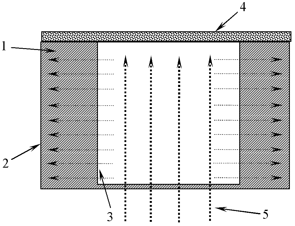
[0033] See attached figure 1 , take 2.5D woven C fiber preform (density 0.56±0.05g / cm 3 ), cut into a circular sample of Φ70 / Φ50)×25, weighed, and put it into a chemical vapor deposition furnace to ensure that the reaction gas diffuses into the C / C green body from the inner surface, and the reaction by-product gas is released from the outer surface. spread out, see figure 1 . Vacuum down to below 50Pa, and heat up to 800-950°C.

[0034] In the first stage, Ar-H2-CH4-TaCl5 reaction gas is passed into the CVD deposition furnace, the deposition time is 20h, and the gas ratio is 800:50:100:0, wherein carbon source gas / tantalum carbide source gas (5 tantalum chloride) with a volume ratio of 1:0; a 1-2 μm thick pure carbon layer is formed on the surface of the carbon fiber; in the second stage, the Ar-H2-CH4-TaCl5 reaction gas is introduced into the CVD deposition furnace, and the deposition time is 100h, the gas ratio is 800:50:100:10~90, wherein the volume ratio of carbon sour...

Embodiment 2

[0038] See attached figure 1 , take a three-dimensional woven fine-woven puncture felt (density 0.80±0.04g / cm 3 ), cut into a circular sample of Φ100 / Φ70×80, weighed, and put it into a chemical vapor deposition furnace to ensure that the reaction gas diffuses into the C / C green body from the inner surface, and the reaction by-product gas flows from the outer surface Spread out. Vacuum down to below 50Pa, heat up to 1400°C, and deposit ZrC-C co-deposition phase in the C / C green body. In the first stage, the Ar-H2-C3H6-ZrCl4 reaction gas is passed into the CVD deposition furnace, the deposition time is 8h, and the gas ratio is 800:50:40:0, wherein carbon source gas / zirconium carbide source gas (four Zirconium chloride) with a volume ratio of 1:0; a 1-2 μm thick pure carbon layer is formed on the surface of the carbon fiber; in the second stage, the Ar-H2-C3H6-ZrCl4 reaction gas is introduced into the CVD deposition furnace, and the deposition time 100h, the gas ratio is 800:5...

Embodiment 3

[0040] See attached figure 1 , take a three-dimensional woven fine-woven puncture felt (density 0.80±0.04g / cm 3 ), cut into a circular sample of Φ100 / Φ70×80, weighed, and put it into a chemical vapor deposition furnace to ensure that the reaction gas diffuses into the C / C green body from the inner surface, and the reaction by-product gas flows from the outer surface Spread out. Vacuum down to below 50Pa, heat up to 1600°C, and deposit HfC-C co-deposition phase in the C / C green body. In the first stage, Ar-H2-C3H6-HfCl4 reaction gas is passed into the CVD deposition furnace, the deposition time is 8h, and the gas ratio is 800:50:40:0, wherein carbon source gas / hafnium carbide source gas (four hafnium chloride) with a volume ratio of 1:0; a 1-2 μm thick pure carbon layer is formed on the carbon fiber surface; in the second stage, the Ar-H2-C3H6-HfCl4 reaction gas is introduced into the CVD deposition furnace, and the deposition time For 60h, the gas ratio is 800:50:40:20~100,...


PUM

PropertyMeasurementUnit
densityaaaaaaaaaa
thicknessaaaaaaaaaa
thicknessaaaaaaaaaa

Abstract

The invention discloses a method for preparing a double-gradient carbide modified C / C composite material. A double-element matrix of carbon and carbide is deposited on the surface of carbon fibers in a carbon fiber preformed body by using a chemical vapor infiltration / deposition process; in the prepared composite material, the density of the carbide is in high-low gradient distribution from the inside diameter surface to the outside diameter surface, and the density of the carbon is in low-high gradient distribution from the inside diameter surface to the outside diameter surface, and thus acarbon-ceramic macro gradient is formed; on the surface of the carbon fibers in the composite material, the whole carbon coating is transited to a carbon-carbide co-deposition coating, finally the whole carbide coating is in gradient distribution, and thus a carbon-ceramic micro gradient is formed; and the double-gradient carbide modified C / C composite material is obtained. The material prepared by the method has the characteristics of excellent high-temperature resistance, abrasion resistance, scouring resistance, oxidation resistance, ablation resistance and thermal shock performance. The method is simple, convenient to operate and low in preparation cost; the prepared C / C composite material has excellent ablation resistance and thermal shock performance; and the method is suitable for industrialized production.

Description

technical field [0001] The present invention relates to a preparation method of a double-gradient carbide modified C / C composite material, in particular to a method for preparing a double-gradient carbide modified C / C composite material by a chemical vapor deposition / infiltration method, which is mainly used for high temperature , high hardness, anti-oxidation, anti-ablation and other requirements of the preparation of functional structural components. Background technique [0002] C / C composite materials have the characteristics of low density, high specific strength, thermal shock resistance, creep resistance, and the strength increases with the increase of temperature between 1000-2200 °C. They have been used in strategic missile warheads, spacecraft return capsules, and space shuttles. It is used in various aircraft such as the leading edge of the wing. However, C / C composites react with an oxidizing atmosphere above 400°C to generate carbon monoxide or carbon dioxide v...

Claims


Application Information

Patent Timeline
Patent Type & Authority Applications(China)
IPC IPC(8): C04B35/83C04B35/622
Inventor 陈招科熊翔张红波李国栋孙威王雅雷
Owner CENT SOUTH UNIV
Why Eureka
Try Eureka