
Unidirectional temporary plugging agent for natural gas wells and application method thereof

An application method and technology of temporary plugging agent, applied in the direction of chemical instruments and methods, composition of drilling holes, etc., can solve the problems of impossibility, complete removal of blockages, etc.

Inactive Publication Date: 2012-07-11
SHENGLI OIL FIELD FANGYUAN CHEM IND
View PDF2 Cites 12 Cited by
  • Summary
  • Abstract
  • Description
  • Claims
  • Application Information

AI Technical Summary

Problems solved by technology

After the construction of these methods is completed, it is necessary to use acidification to remove the blockage, but it is impossible to completely remove the blockage

Method used

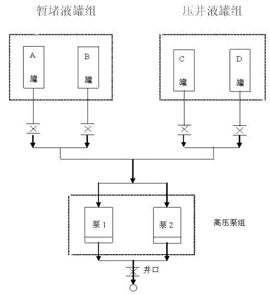
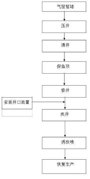
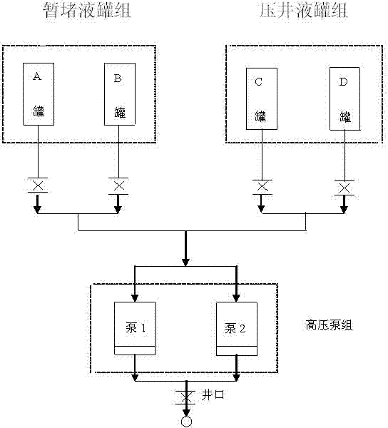

Image

  • Unidirectional temporary plugging agent for natural gas wells and application method thereof
  • Unidirectional temporary plugging agent for natural gas wells and application method thereof
  • Unidirectional temporary plugging agent for natural gas wells and application method thereof

Examples


Embodiment 1

[0018] Weigh 20 - 6000g of 22% acrylamide aqueous solution (you can also make acrylamide, water and other reactants directly into a mixed solution without pre-preparing acrylamide aqueous solution), tetraallyl ammonium bromide 2.0g, Na 2 CO 3 300g, activated clay 300g, stirred and dispersed for 60 minutes, heated to 40°C, filled with nitrogen for 30 minutes, added initiator k 2 S 2 o 8 -NaHSO 3 5-6g polymerized. After 2 hours of polymerization, the polymerized elastic colloid was kept at 85° C. for 8 hours. Cut the heated colloid to a length of 0.5 ~ The 1.0mm blocks were dried to obtain dry powder. Take 2000g of the dry powder prepared by the above method, add 200g of polycondensed propylene oxide-dimethylamine and 20g of o-phenylenediamine, stir and infiltrate for 2 hours to obtain the finished product.

Embodiment 2

[0020] Weigh 5000g of 20-22%% acrylamide aqueous solution, 1g of N, N-methylenebisacrylamide, 300g of α-hydroxysulfonate, activated silica 200g, stirred and dispersed for 60 minutes, heated to 30°C, filled with nitrogen for 30 minutes, added initiator k 2 S 2 o 8 -NaHSO 3 5-6g polymerized. After polymerizing for 1 hour, the polymerized elastic colloid was kept at a constant temperature of 70°C for 10 hours. Cut the heated colloid to a length of 0.5 ~ The 1.0mm blocks were dried to obtain dry powder. Get 1000g of dry powder worth the above method. Add 200g of polycondensed propylene oxide-dimethylamine and 10g of o-phenylenediamine to the dry powder, stir and infiltrate for 2 hours to obtain the finished product.

Embodiment 3

[0022] Weigh 7500g of 20-22% acrylamide aqueous solution, 5g of divinylbenzene, 500g of sultone, 500g of active silicon dioxide, stir and disperse for 60 minutes, heat to 30°C, fill with nitrogen for 30 minutes, add the initiator Na 2 S 2 o 8 -NaHSO 3 8-10g polymerized. After 3 hours of polymerization, the polymerized elastic colloid was kept at 90° C. for 6 hours. Cut the heated colloid to a length of 0.5 ~ The 1.0mm blocks were dried to obtain dry powder. Take 3000g of dry powder worth the above method, add polycondensed propylene oxide-dimethylamine 200g, o-phenylenediamine 10g, stir and infiltrate for 2 hours to get the finished product.


PUM

PropertyMeasurementUnit
lengthaaaaaaaaaa

Abstract

The invention relates to a unidirectional temporary plugging agent used for extracting natural gas from wells of an oil field and an application method. The temporary plugging agent comprises hydrophilic high polymer powder, wherein a polymeric monomer of the hydrophilic high polymer powder is one from or a combination of several from acrylamide, acrylate, propylene sulfonate, ethylene sulfonate,2-acrylamido-2-methyl propane sulfonic acid (AMPS) and vinyl pyrrolidone. The temporary plugging agent is matched with well killing fluid for use after being made into temporary plugging fluid, can form a leakage-free working fluid system with a differential pressure of 30MPa, and can be completely suitable for low pressure natural gas wells of which the pressure coefficient is between 0.2 and 0.5, the temperature is not higher than 180 DEG C and the differential pressure is not larger than 30MPa.

Description

technical field [0001] The invention relates to a one-way temporary plugging agent material used in oil fields to exploit natural gas from wells, in particular to a one-way temporary plugging agent suitable for natural gas wells and an application method thereof. Background technique [0002] During the exploitation of natural gas, with the increase of production volume, the energy of the gas layer is getting lower and lower, and the pressure coefficient has been reduced to 0.2 ~ 0.5, in the maintenance process of these gas wells, the leakage of fluid entering the well and the damage to the gas layer after leakage are difficult problems to solve. One-way temporary plugging of low-pressure leakage gas wells is the primary measure to ensure normal production of gas fields. At present, the methods for preventing the loss of fluids entering the well for low-pressure natural gas mainly include milk of lime plugging method, cement plugging method and other similar methods. After...

Claims


Application Information

Patent Timeline
Patent Type & Authority Applications(China)
IPC IPC(8): C09K8/44C08F220/56C08F226/02C08F222/38C08F212/36C08F228/02C08F2/44
Inventor 韩荣山孙莲美杨涛孟维斌马超刘善祥白明友郭立发
Owner SHENGLI OIL FIELD FANGYUAN CHEM IND
Learn More