
Rail pressure control method for gasoline direct injection engine common rail fuel system

A fuel system and control method technology, applied in engine control, fuel injection control, electrical control, etc., can solve the problem of increasing the difficulty of adjusting control algorithm parameters, heavy workload, and lack of detailed consideration of the structure and characteristics of the common rail fuel system And other issues

Active Publication Date: 2012-07-11
JILIN UNIV
View PDF6 Cites 17 Cited by
  • Summary
  • Abstract
  • Description
  • Claims
  • Application Information

AI Technical Summary

Problems solved by technology

[0004] 2. The conventional development process of ECU requires a lot of experience and calibration tests, the workload is heavy, the influence of human subjective factors is relatively large, and the system development cycle is long;
[0005] 3. The calibrated control algorithm has different anti-disturbance capabilities for factors such as parameter uncertainty
Although this method introduces the idea of ​​fuzzy control on the basis of the original PID control algorithm, which improves the robustness of the system to a certain extent, it does not consider the structure and characteristics of the common rail fuel system in detail, which increases the The difficulty of adjusting the parameters of the control algorithm

Method used


Image

  • Rail pressure control method for gasoline direct injection engine common rail fuel system
  • Rail pressure control method for gasoline direct injection engine common rail fuel system
  • Rail pressure control method for gasoline direct injection engine common rail fuel system

Examples


Embodiment Construction

[0062] The present invention is described in detail below in conjunction with accompanying drawing:

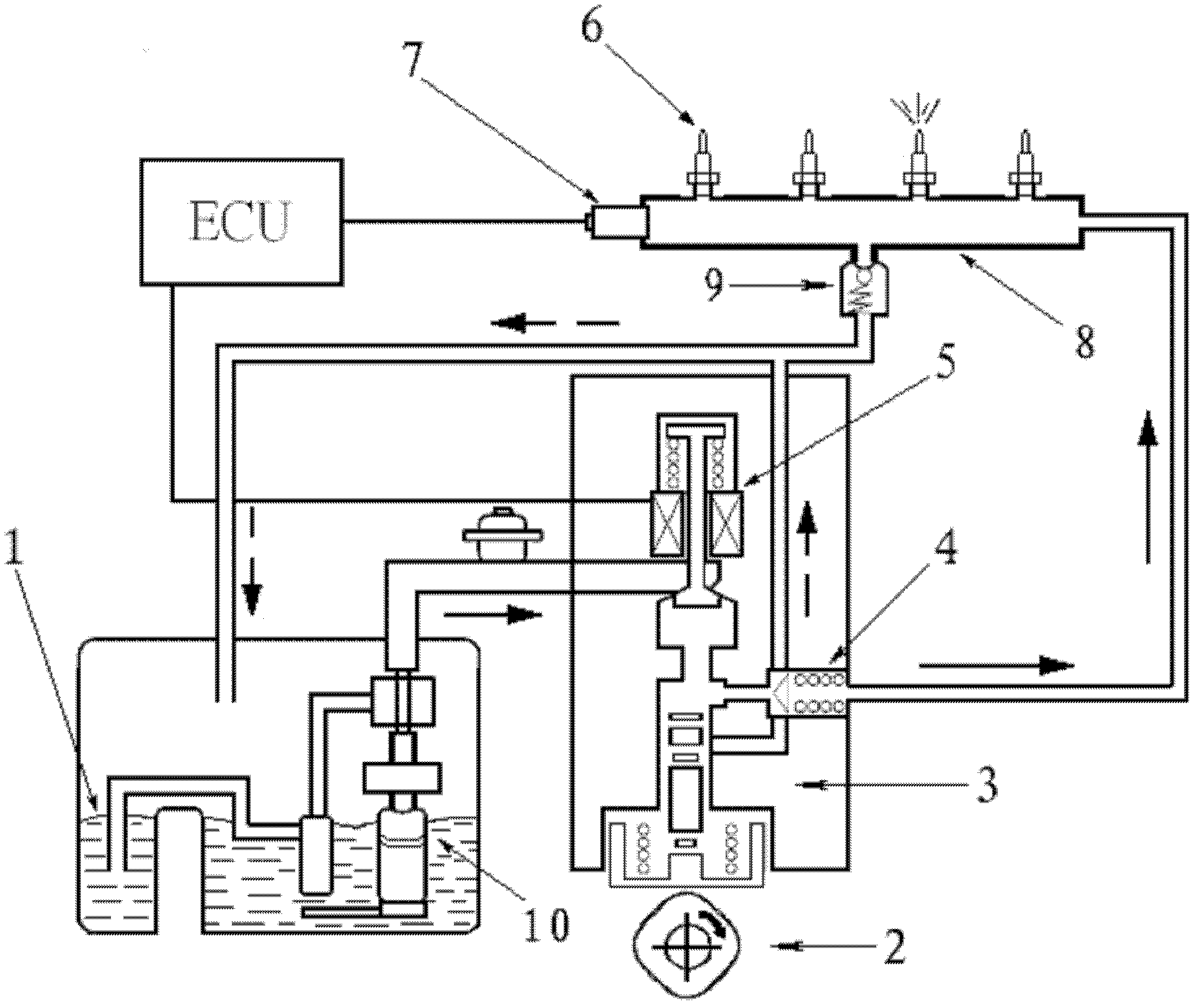
[0063] refer to figure 2 , The invention provides a rail pressure control method for a common rail fuel system of a direct injection gasoline engine, which can achieve a better rail pressure control effect. The common rail fuel system is the most important part of the fuel supply system of the direct injection gasoline engine. Better fuel injection effect can also be obtained at low speeds. The basic structure of the direct injection gasoline engine common rail fuel system includes fuel tank 1, cam 2, high pressure pump 3, check valve 4, pressure control valve 5, fuel injector 6, rail pressure sensor 7, common rail 8, pressure limiting valve 9, Low-pressure electric fuel pump 10 and electronic control unit ECU.

[0064] The common rail fuel system of a direct injection gasoline engine is quite different from that of a traditional port injection engine. 2 The fuel oil flow...


PUM


Abstract

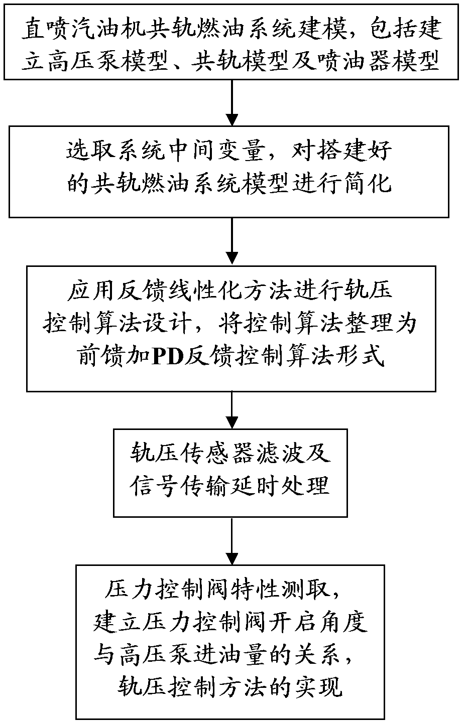
The invention discloses a rail pressure control method for a gasoline direct injection engine common rail fuel system, which includes: the first step, building a mathematical model of the gasoline direct injection engine common rail fuel system, namely building a mathematical model of a high-pressure pump, then building a common rail mathematical model and finally building a mathematical model of a fuel injector; the second step, simplifying the mathematical model of the common rail fuel system; the third step, designing the control algorithm and regulating the form of the control algorithm on the basis of the mathematical model of the common rail fuel system; the fourth step, filtering by a rail pressure sensor and delaying signal transmission, namely acquiring rail pressure signals by an AD (analog-digital) passage of a single-chip microcomputer and removing individual error points and signal interference by the filter algorithm, and then designing signal tests for the rail pressure sensor (7); the fifth step, testing characteristics of a pressure control valve, converting the output of the control algorithm into action time of the pressure control valve, namely testing the characteristics of the pressure control valve (5) to acquire relation between the switching delay of the pressure control valve (5) and voltage of a vehicular storage battery and then building the relation between the opening angle of the pressure control valve (5) and the flow of the high-pressure pump (3).

Description

technical field [0001] The invention relates to a control method belonging to the technical field of engine electronic control, more specifically, the invention relates to a rail pressure control method of a common rail fuel system of a direct injection gasoline engine. Background technique [0002] The ECU (Electronic Control Unit) of the automobile engine is one of the core components for the normal operation of the engine. The introduction of various energy-saving and emission-reduction technologies today makes the ECU more powerful, which greatly increases the difficulty of ECU development. The main Have the following questions: [0003] 1. The introduction of various complex electronic control components has increased the coupling degree of various components in the system. According to the previous calibration method, the development workload of ECU has been greatly increased, such as exhaust gas recirculation EGR (Exhaust Gas Recirculation), variable valve positive V...

Claims


Application Information

Patent Timeline
Patent Type & Authority Applications(China)
IPC IPC(8): F02D41/38
Inventor 陈虹欣白宇胡云峰
Owner JILIN UNIV
Learn More