Device for measuring transmittance of optical window of nuclear fusion device

An optical window and measurement device technology, applied in the field of optical measurement, can solve the problems of reducing the accuracy and reliability of data processing, measuring the transmittance of optical windows, reducing the transmittance of optical windows, etc., so as to prevent contamination and ensure representative performance, ensuring stability

Active Publication Date: 2014-07-23
SOUTHWESTERN INST OF PHYSICS
View PDF9 Cites 0 Cited by
  • Summary
  • Abstract
  • Description
  • Claims
  • Application Information

AI Technical Summary

Problems solved by technology

[0003] In the process of plasma discharge, glow discharge cleaning and silicide wall treatment, the optical window will be polluted by factors such as sputtering and spraying, which will reduce the transmittance of the optical window, and the above pollution factors will also affect the light of different wavelengths. have different effects
In the existing field of nuclear fusion, there is no device capable of measuring the transmittance of optical windows that may be contaminated, which reduces the accuracy and reliability of subsequent data processing such as laser scattering measurement of electron temperature and density, and plasma effective charge number.

Method used


Image

  • Device for measuring transmittance of optical window of nuclear fusion device
  • Device for measuring transmittance of optical window of nuclear fusion device

Examples


Embodiment 1

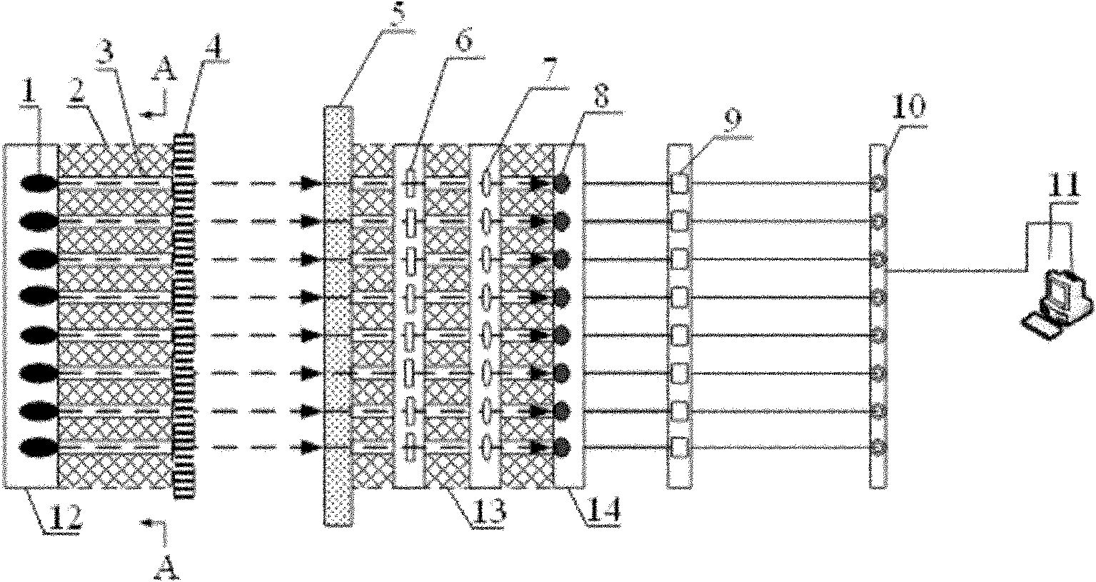
[0031] Such as figure 1 As shown, the optical window transmittance measurement device of the nuclear fusion device in this embodiment includes a light source module, a detection module, a data acquisition device 10 and a data analysis device 11 . Wherein, the light source module is located inside the optical window 5 of the nuclear fusion device, namely figure 1 On the left side of the middle optical lens 5, the detection module is located outside the optical window 5 of the nuclear fusion device, namely figure 1 On the right side of the middle optical lens 5 , the detection module transmits signals to the data collection device 10 , and the data analysis device 11 receives various signals from the data collection device 10 .

[0032] In this embodiment, the nuclear fusion device is the China Circulator No. 2 A (HL-2A) device, and other fusion devices can also be used, and the optical window 5 is the scattering of the incoherent laser Thomson scattering system on the HL-2A de...

Embodiment 2

[0044] The difference between this embodiment and embodiment 1 is:

[0045] The light source module in this embodiment further includes a stepping motor, which is connected with the shielding plate 4 to control the movement of the shielding plate 4 . During the measurement period, the stepping motor controls the baffle plate 4 to be in an open state, that is, the stepping motor rotates to open the baffle plate 4 to a position 120 degrees from the end face of the light source collimating light-passing component 2, and does not block the light source collimating light-passing hole 3; During the non-measurement period, the stepper motor controls the baffle plate 4 to be in the closed state, completely blocking the light source and collimating the light hole 3 .

[0046] The above technical features can conveniently and quickly control the opening / closing state of the shielding plate 4 .

Embodiment 3

[0048] The difference between this embodiment and the above two embodiments is:

[0049] In the detection module of this embodiment, a narrow-band interference filter 6 is arranged on each detection collimation aperture, and the central wavelength parameter of the narrow-band interference filter 6 is the same as the emission central wavelength of the LED light-emitting diode 1 at the corresponding position. same.

[0050] The above technical features enhance the monochromaticity of light received by the photodetector 8;


PUM


Abstract

The invention belongs to the field of optical measurement and particularly relates to a device for measuring the transmittance of an optical window of a nuclear fusion device. The device disclosed by the invention comprises a light source module, a detection module, data collecting equipment (10) and data analyzing equipment (11), wherein the light source module is located at the inner side of the optical window (5) of the nuclear fusion device; the detection module is located at the outer side of the optical window (5) of the nuclear fusion device; signals are transmitted to the data collecting equipment (10) by the detection module; and various paths of the signals of the data collecting equipment (10) are received by the data analyzing equipment (11). With the adoption of the device disclosed by the invention, the aim of measuring the transmittance of the optical window of the nuclear fusion device can be achieved, and the technical effects of accurately measuring the transmittance of lights passing through the polluted optical window within wavelength ranges of a visible light wave band and an infrared wave band can be achieved.

Description

technical field [0001] The invention belongs to the field of optical measurement, in particular to a device for measuring the transmittance of an optical window of a nuclear fusion device. Background technique [0002] In the study of magnetic confinement nuclear fusion, the optical diagnostic system needs to use different optical glass windows, such as the incident and exit windows of the laser beam and the reception and detection windows of the scattered signals of the incoherent Thomson scattering system and the coherent Thomson scattering system. The incoherent Thomson scattering system uses a Q-switched high-power pulsed laser, and the plasma electron temperature data can be obtained by measuring the scattering spectral distribution function, and the electron density data can be obtained after the total intensity of the scattered light pulse is calibrated. In the visible light band with a wavelength range of 400-760nm or the near-infrared band with a wavelength range of...

Claims


Application Information

Patent Timeline
Patent Type & Authority Patents(China)
IPC IPC(8): G01M11/02
Inventor 刘春华黄渊冯震
Owner SOUTHWESTERN INST OF PHYSICS
Why Eureka
Try Eureka