Continuous-laser driving device and method
A driving device and driving method technology, applied in the direction of lasers, laser components, semiconductor lasers, etc., to achieve the effect of reducing equivalent heating power, reducing the requirements of response speed, and fast response speed
- Summary
- Abstract
- Description
- Claims
- Application Information
AI Technical Summary
Problems solved by technology
Method used
Image
Examples
Embodiment 1
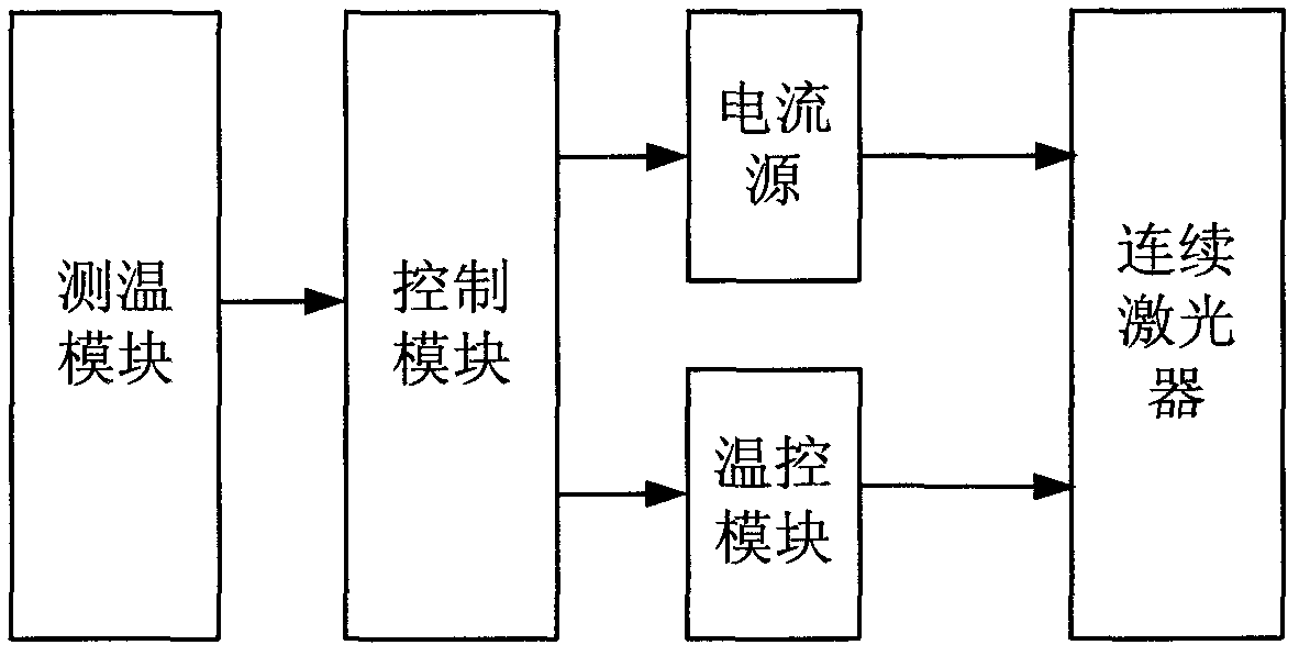
[0039] figure 1 A basic structure diagram of a continuous laser drive device according to an embodiment of the present invention is schematically given. like figure 1 As shown, the drive unit includes:
[0040] A current source, the current source is used to output an operating current to the continuous laser, such as a rectangular wave electrical signal, a triangular wave electrical signal, a sine wave electrical signal, and the like. The current source is a prior art in this field, and will not be repeated here. Optionally, the continuous laser is a quantum cascade laser, and the continuous laser can be packaged in TO-3 or HHL. The continuous laser can also be a conventional semiconductor laser, such as VCSEL, DFB and other semiconductor lasers, which is easily understood by those skilled in the art.
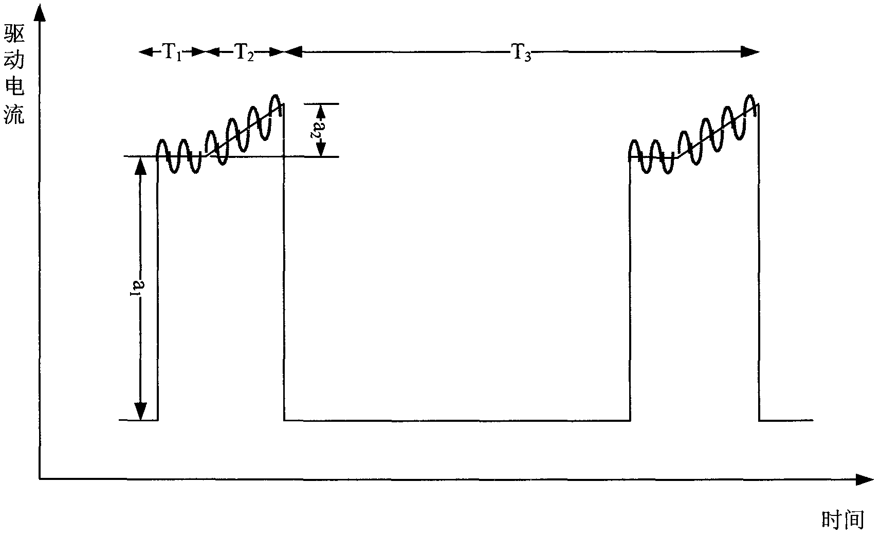
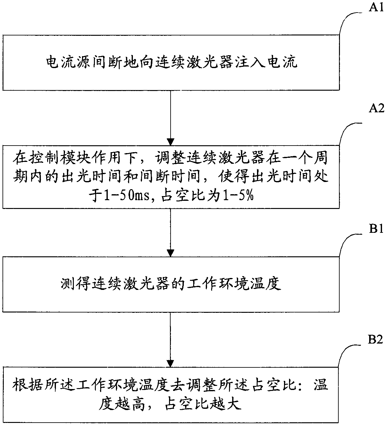
[0041] A control module, the control module is used to adjust the intermittent time and output time (corresponding to the light output time of the laser) of the current so...
Embodiment 2
[0059] According to the application example of the driving device and method in embodiment 1 of the present invention in a laser gas analyzer, specifically, the quantum cascade laser gas analyzer is used to measure SO in a sulfuric acid plant. 2 concentration. The sample gas in this working condition contains SO 2 , SO 3 Such as acid gas and moisture, the pretreatment system used in the traditional sampling instrument is severely corroded in this place, and leakage will occur in severe cases. Moreover, when the sample gas is transported in the sampling pipeline, crystals will precipitate out, causing the sampling system to often be blocked. Therefore, the use of in-situ measurement laser gas analyzers has outstanding advantages in this working condition. However, traditional near-infrared laser gas analyzers cannot effectively measure SO 2 and other gases, so a quantum cascade laser gas analyzer working in the infrared band was used to measure the SO in the sulfuric acid p...
Embodiment 3
[0073] The application example of the driving device and method according to Embodiment 1 of the present invention in a laser gas analyzer is specifically applied in the measurement of escaped ammonia in a denitrification device.
[0074] Reduce NO x Emissions are one of the main tasks of environmental protection and prevention. Now, a certain amount of NH is generally injected before the flue gas is discharged. 3 with NO x reaction to generate environmentally friendly N 2 and H 2 O to reduce NO x emissions. But in this denitrification process, excess NH 3 The amount of (slip ammonia) needs to be precisely monitored and controlled to avoid excess NH 3 It will lead to secondary environmental pollution and affect the normal operation of denitrification equipment in severe cases.
[0075] However, the temperature of the denitrification process point is high (about 380°C), and the dust is high (dust content 10-50g / Nm 3 ), high humidity (water vapor content 10-20%), NH 3 ...
PUM
 Abstract
Description
Claims
Application Information
 - R&D
- Intellectual Property
- Life Sciences
- Materials
- Tech Scout
- Unparalleled Data Quality
- Higher Quality Content
- 60% Fewer Hallucinations
Browse by: Latest US Patents, China's latest patents, Technical Efficacy Thesaurus, Application Domain, Technology Topic, Popular Technical Reports.
© 2025 PatSnap. All rights reserved.Legal|Privacy policy|Modern Slavery Act Transparency Statement|Sitemap|About US| Contact US: help@patsnap.com


