
Laser welding device

A technology of laser welding and equipment, which is applied in the direction of laser welding equipment, welding equipment, laser devices, etc., can solve the problems of inability to absorb the effective part of the laser beam, poor welding structure, material spatter, etc., and achieve improved welding efficiency and welding quality, easy The effect of absorbing and avoiding material splash

Inactive Publication Date: 2012-07-18
SHENZHEN GDLASER TECH CO LTD
View PDF8 Cites 7 Cited by
  • Summary
  • Abstract
  • Description
  • Claims
  • Application Information

AI Technical Summary

Problems solved by technology

However, using a high energy pulse before reaching the melting temperature can lead to rather low efficiency, since the active part of the laser beam cannot be absorbed at the beginning of the pulse; without effective absorption efficiency there is no point in talking about good or bad welding results
Also, once the laser pulse is coupled to the material, this very high peak power can be applied too much, causing spattering of the material (radiation droplets that melt the metal) or causing unwanted evaporation of metal and alloy components
This undesired inefficiency and spatter can cause poor weld construction

Method used


Image

  • Laser welding device
  • Laser welding device
  • Laser welding device

Examples


Embodiment Construction

[0017] The present invention will be described in further detail below through specific embodiments and in conjunction with the accompanying drawings, but the protection scope of the present invention should not be limited thereto.

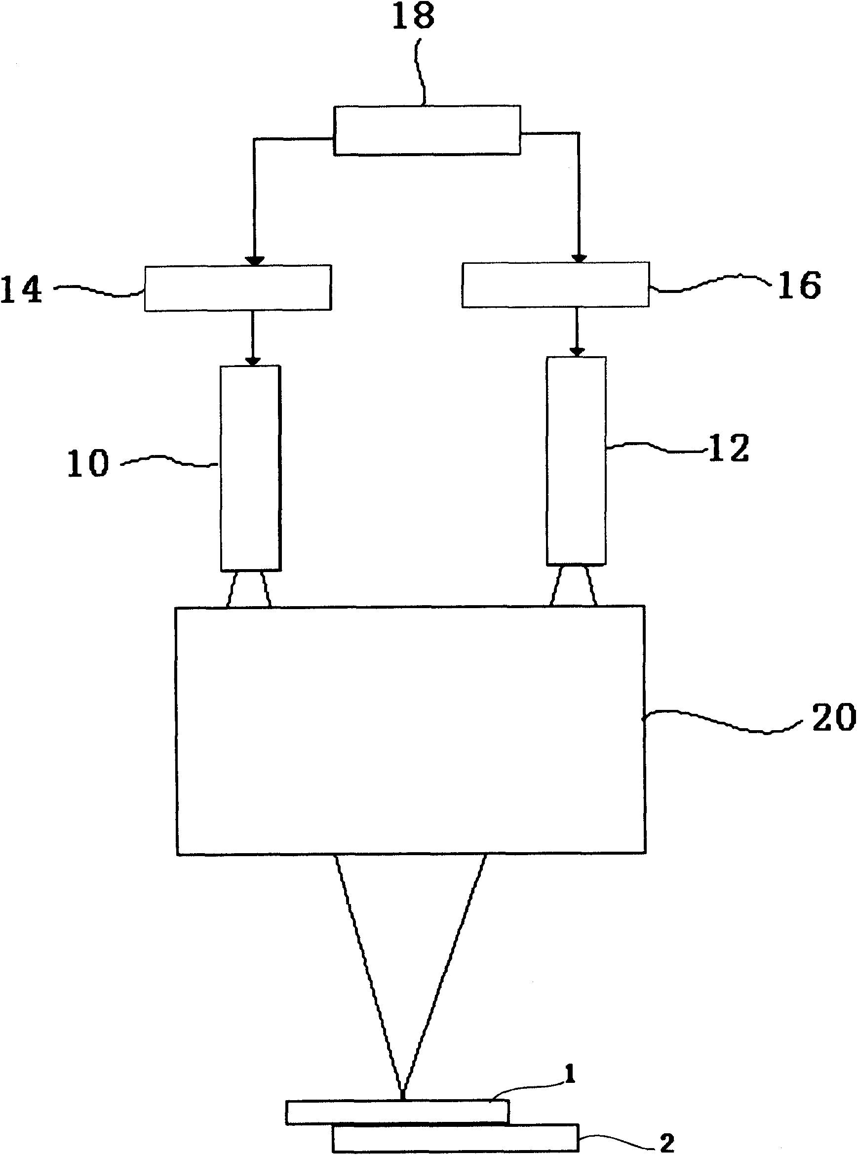
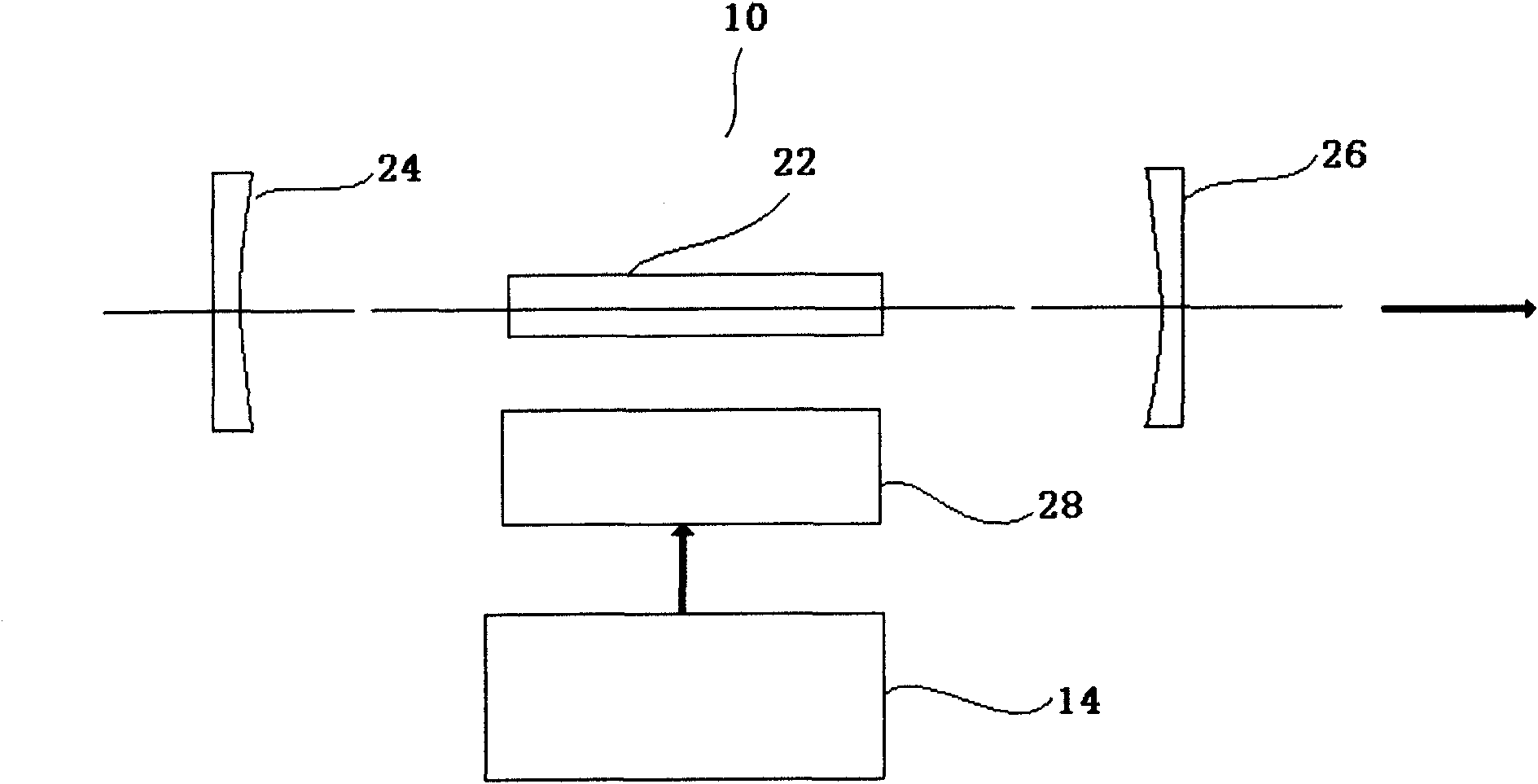
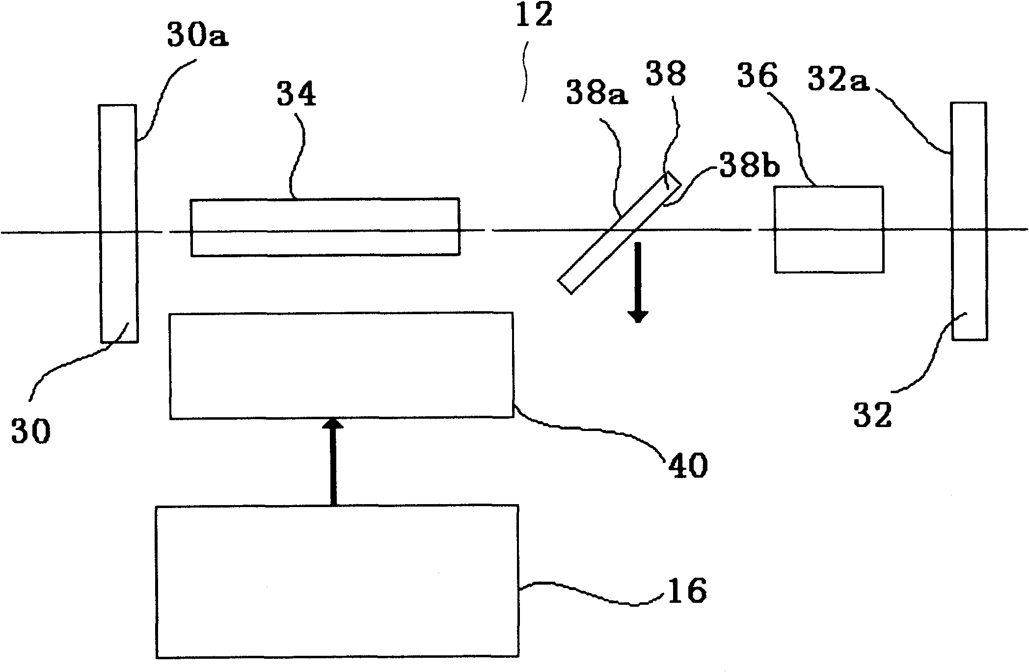
[0018] figure 1 It is a simplified block diagram of laser welding equipment that couples and focuses two laser beams with different wavelengths according to an embodiment of the present invention. The laser welding equipment includes: Nd:YAG fundamental wave resonator 10 and Nd:YAG harmonic resonator 12, which are used to generate fundamental wave and harmonic respectively; laser power supply 14 of fundamental wave resonator and laser power supply of harmonic resonator 16, respectively connected with the electro-optical pumping device on the fundamental wave resonator 10 and the harmonic resonator 12; the control unit 18 is used to control the laser power supply 14 of the fundamental wave resonator and the laser power supply 16 of the harmonic res...


PUM

PropertyMeasurementUnit
wavelengthaaaaaaaaaa

Abstract

The invention discloses a laser welding device, which comprises a fundamental wave resonance cavity, a harmonic resonance cavity, a control unit and a coupling device. The fundamental wave resonance cavity is used for generating a first laser beam with variable pulse widths and a fundamental wave length, the harmonic resonance cavity is used for generating a second laser beam with variable pulse widths and a harmonic wave length, the control unit is used for controlling respective laser power supplies of the fundamental wave resonance cavity and the harmonic resonance cavity and further controlling the laser emitting sequence of the fundamental wave resonance cavity and the harmonic resonance cavity, so that emission of the second laser beam is slightly prior to emission of the first laser beam, and the coupling device is used for coupling the first laser beam and the second laser beam which are focused on a workpiece to be welded through the same focusing lens. By the aid of the laser welding device, metal and alloy with high reflection coefficient can be effectively welded.

Description

technical field [0001] The invention relates to a laser welding equipment for welding metals with laser beams, in particular to a laser welding equipment for welding metals or alloys with high reflection coefficients by using two laser beams with different wavelengths. Background technique [0002] In recent years, lasers have been widely used in industrial production, especially for welding, cutting, drilling, marking and surface treatment of metals. In production, laser welding technology is becoming more and more important, mainly due to the high precision, high processing rate, low thermal stress on the workpiece and the degree of automation that laser welding can achieve. [0003] There are generally two types of laser light sources most widely used in current laser welding equipment. The first is a gas laser, namely carbon dioxide (CO 2 ) laser, the laser wavelength is 10.6 microns. The second is a solid-state laser, namely Nd:YAG (Nd:YAG 3 al 5 o 12 , Nd-doped y...

Claims


Application Information

Patent Timeline
Patent Type & Authority Applications(China)
IPC IPC(8): B23K26/20B23K26/06H01S3/23B23K26/064B23K26/21
Inventor 叶毅聪
Owner SHENZHEN GDLASER TECH CO LTD
Learn More