
Isolated rapid turn-off metal oxide field effect transistor (MOFET) driving circuit

A drive circuit, isolation technology, applied in the field of power electronics drive applications, can solve the problems of slow turn-off speed, fixed or little change in duty cycle, low requirements for anti-interference, etc., to achieve accelerated turn-off, voltage stability, The effect of preventing electrostatic breakdown

Inactive Publication Date: 2012-07-18
JIANGSU UNIV
View PDF4 Cites 34 Cited by
  • Summary
  • Abstract
  • Description
  • Claims
  • Application Information

AI Technical Summary

Problems solved by technology

Therefore, the traditional magnetic coupling drive circuit is only suitable for occasions where the anti-interference requirements are not high, the turn-off speed is slow, and the duty cycle is fixed or does not change much.

Method used


Image

  • Isolated rapid turn-off metal oxide field effect transistor (MOFET) driving circuit
  • Isolated rapid turn-off metal oxide field effect transistor (MOFET) driving circuit
  • Isolated rapid turn-off metal oxide field effect transistor (MOFET) driving circuit

Examples


Embodiment Construction

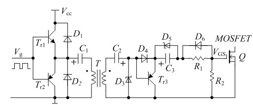
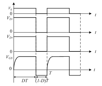
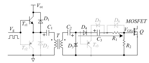
[0016] figure 1 In, NPN transistor T r1 The collector is connected to the positive power supply, the emitter and the PNP transistor T r2 The emitter is connected to form a totem pole output, which is used to amplify the power and improve the driving ability of the circuit. The diode D 1 and diode D 2 respectively and the transistor T r1 and transistor T r2 Parallel connection, play the role of freewheeling when inductive load. DC blocking capacitor C 1 The positive polarity end is connected to the output point of the totem pole, and the negative polarity end is connected to the same-named end of the primary side of the high-frequency isolation transformer T to prevent the DC component from passing through and avoid DC magnetization and saturation of the transformer. Secondary capacitance C 2 The negative terminal is connected to the terminal with the same name on the secondary side of the high-frequency isolation transformer T, and the positive terminal is connected to ...


PUM


Abstract

The invention discloses an isolated rapid turn-off metal oxide field effect transistor (MOFET) driving circuit, which comprises a totem-pole output circuit, a transformer T, a negative voltage generation circuit and an MOSFET, wherein an output point of the totem-pole output circuit is connected with the primary dotted terminal of the transformer T through the anode of a blocking capacitor C1; the secondary dotted terminal of the transformer T is sequentially connected in series with a secondary capacitor C2, a diode D4, an electrolytic capacitor C3, a resistor R1 and the MOSFET, and then is connected to the secondary unlike terminal of the transformer T; a voltage stabilizing diode D3 is connected to the two ends of the secondary side of the transformer T; the base of a triode Tr3 is connected with the anode of the secondary capacitor C2, the collector of the triode Tr3 is connected with the cathode of the diode D4, and the emitter of the triode Tr3 is connected with the secondary unlike terminal of the transformer T; a diode D6 is reversely connected in parallel with the two ends of the gate input resistor R1; a voltage stabilizing diode D5 is connected in parallel with the two ends of the electrolytic capacitor C3; and a resistor R2 is connected between the gate and source of the MOSFET. The circuit is applied to places with high requirements on the anti-interference capability of the driving circuit and on rapid turn-off and with large duty ratio variation ranges.

Description

technical field [0001] The invention belongs to the technical field of power electronics drive applications, and in particular relates to an isolated MOSFET drive circuit that can be quickly turned off. occasion. Background technique [0002] At present, the commonly used power converter circuit driver chips are expensive and have certain limitations in different special applications. The power MOSFET (Metal Oxide Semiconductor Field Effect Transistor) is a voltage-type control device. As long as the voltage applied between the gate and the source exceeds its threshold voltage, it will be turned on. Due to the junction capacitance of the MOSFET, its drain and source The sudden rise of the voltage across the pole will generate an interference voltage across the gate and source through the junction capacitance. The traditional magnetically coupled MOSFET drive circuit includes two triodes, a DC blocking capacitor, a transformer, a gate input resistor and a voltage regulator ...

Claims


Application Information

Patent Timeline
Patent Type & Authority Applications(China)
IPC IPC(8): H02M1/08
Inventor 廖志凌施卫东梅从立宋中奇刘国海
Owner JIANGSU UNIV
Learn More