Milling cutter for processing flexible board

A flexible board and milling cutter technology, applied in milling cutters, metal processing equipment, manufacturing tools, etc., can solve the problems of poor rigidity of milling cutters, poor cutting performance, and inability to meet the milling accuracy of groove bottom and chamfering surface at the same time, and achieve Increased service life, high processing efficiency, and improved milling quality

Active Publication Date: 2014-11-12
ZHEJIANG DEWEI CEMENTED CARBIDE MFG CO LTD
View PDF9 Cites 1 Cited by
  • Summary
  • Abstract
  • Description
  • Claims
  • Application Information

AI Technical Summary

Problems solved by technology

[0006] For this reason, the technical problem to be solved by the present invention is that the existing milling cutters for processing flexible circuit boards have poor rigidity and poor cutting performance, and cannot satisfy the milling accuracy of the bottom of the groove and the chamfering surface at the same time. , high processing efficiency, strong durability, good dimensional accuracy and edge quality milling cutter

Method used


Image

  • Milling cutter for processing flexible board
  • Milling cutter for processing flexible board
  • Milling cutter for processing flexible board

Examples


Embodiment 1

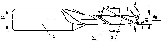
[0032] figure 1 Shown is a milling cutter for processing flexible boards according to the present invention, which includes a tool holder 1, one end of which is extended into a milling cutter head 2, and the surface of the milling cutter head 2 is formed with two circles in the same direction. The spiral groove 3 forms a milling edge, and the end of the milling bit 2 is provided with a cutting surface of a V mouth; the end of the cutting surface is provided with a chamfer to form a chamfer edge; the angle of the chamfer is 45 °, The angle ω of the helix angle of the helical groove 3 is 30°.

[0033] The outer diameter φD of the shank 1 is 3.175 mm, the outer diameter φd of the milling head 2 is 1.8 mm, and the core circle diameter φK of the milling head 2 is 50% of the outer diameter φd of the milling head 2, That is 0.9mm.

[0034] The milling cutter is formed with double-ended teeth, such as figure 2 Shown is the A-A view obtained by cutting along the direction perpendic...

Embodiment 2

[0049] Embodiment 1 of the milling cutter for processing flexible boards in this embodiment is basically the same, and the difference lies in:

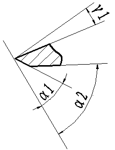
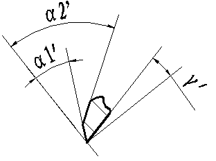
[0050] The angle ω of the helix angle of the helical groove 3 is 32°. The milling cutter is formed with double-end teeth, one end tooth relief angle α1 is 13°, the other end tooth relief angle α2 is 29°, and the end tooth rake angle γ1 is 4°. The side of the chamfering edge is formed with double-end teeth, wherein the chamfering relief angle α1' of one end tooth is 10°, and the chamfering relief angle α2' of the other end tooth is 27°. The rake angle γ1' is 4°. The rake angle γ of the milling cutter is 4°. , the outer diameter φD of the tool holder 1 is 3.175mm, and the outer diameter φd of the milling head 2 is 0.4mm. The core diameter φK of the milling head 2 is 0.20 mm. The distance e between one edge of the end teeth of the milling cutter and the center is 0.02 mm. The end tooth of the milling cutter is a Closed groove type, ...

Embodiment 3

[0052] Embodiment 1 of the milling cutter for processing flexible boards in this embodiment is basically the same, and the difference lies in:

[0053] The angle ω of the helix angle of the helical groove 3 is 28°. The milling cutter is formed with double-end teeth, wherein one end tooth relief angle α1 is 17°, the other end tooth relief angle α2 is 31°, and the end tooth relief angle γ1 is 8°. The chamfering edge is formed with double-ended teeth, wherein the chamfering relief angle α1' of one end tooth is 14°, and the chamfering relief angle α2' of the other end tooth is 29°. The angle γ1' is 8°. The rake angle γ of the milling cutter is 8°. The outer diameter φD of the tool holder 1 is 3.175mm, and the outer diameter φd of the milling head 2 is 3.175mm. The core circle diameter φK of the milling head 2 is 1.59mm. The distance e between one edge of the end teeth of the milling cutter and the center is 0.09 mm. The end tooth of the milling cutter is a Closed groove type,...


PUM


Abstract

The invention discloses a milling cutter for a processing flexible board, which comprises a cutter handle (1). One end of the cutter handle (1) extends to form a milling cutter head (2). Two spiral grooves (3) in the same spiral direction are molded on the surface of the milling cutter head (2) to form milling edges. A V-notch cutting surface is arranged at the end of the milling cutter head (2). A chamfer is arranged at the end part of the cutting surface to form a chamfering edge. The spiral angle omega of each spiral groove (3) is 28-32 degrees. The milling cutter solves the problems of poor rigidity and poor cutting performance of the existing milling cutter used for processing flexible circuit boards, and is particularly suitable for processing blind grooves with chamfers on plates such as aluminum substrates, copper substrates, flexible boards, Teflon plates and polytetrafluoroethylene plates.

Description

technical field [0001] The invention belongs to the field of milling cutter design and manufacture, in particular to a milling cutter for processing flexible boards. Background technique [0002] The traditional printed circuit board is mainly composed of copper foil, glass fiber, epoxy resin and related fillers. The chip breaking design of the rhombic tooth milling cutter achieves the above-mentioned good performance. But now, printed circuit boards are gradually replaced by soft substrate materials such as aluminum substrates. This kind of board does not contain glass fiber, and is mainly composed of copper foil, insulating materials, and aluminum board. The processed board is relatively soft. If you still use it before PCB processing The chip breaker and ordinary 2-edge flat-bottom milling cutter are not easy to form chip breaking during machining and are more likely to adhere to the cutting edge to form built-up chips and rapidly deteriorate the cutting environment, res...

Claims


Application Information

Patent Timeline
Patent Type & Authority Patents(China)
IPC IPC(8): B23C5/10
Inventor 王辉
Owner ZHEJIANG DEWEI CEMENTED CARBIDE MFG CO LTD
Why Eureka
Try Eureka