Thermal-radiation internal-circulation power generation device
What is Al technical title?
Al technical title is built by PatSnap Al team. It summarizes the technical point description of the patent document.
A power generation device and internal circulation technology, applied in solar thermal power generation, machines/engines, and mechanical power generation with solar energy, etc., can solve the problems of traditional backward mode, low heat conversion efficiency, easy heat dissipation, etc., and achieve no scale, boiling point, etc. High, fast heating effect
Active Publication Date: 2013-09-11
河北正能锅炉设备有限公司
View PDF6 Cites 0 Cited by
Summary
Abstract
Description
Claims
Application Information
AI Technical Summary
This helps you quickly interpret patents by identifying the three key elements:
Problems solved by technology
Method used
Benefits of technology
Problems solved by technology
At present, power generation devices on the market mainly use single thermal power, single hydraulic power, single solar power, and single nuclear energy to generate electricity. Their models are traditionally outdated, with low heat conversion efficiency and easy loss of heat energy, resulting in energy waste.
Method used
Image
Click on the blue label to locate the original text in one second.
Reading with bidirectional positioning of images and text.
Examples
Embodiment 1
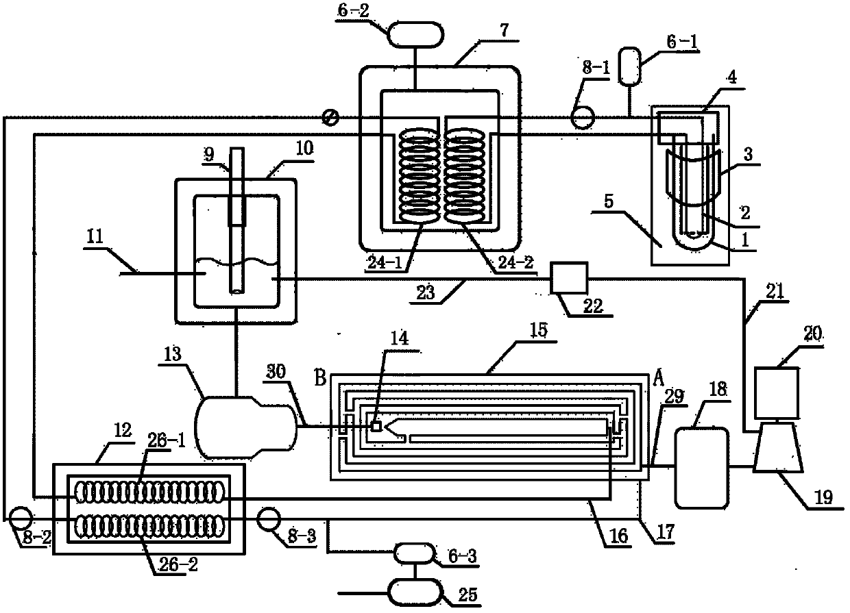
[0032] Tube heat radiation internal circulation power generation device: when the sun is sufficient, such as figure 1As shown, the solar tube 5 is connected to the first heat conduction coil 24-2 in the energy storage tank 7 through the inlet and outlet through two pipes in the connection box 4 . The energy storage tank 7 has an insulation layer and is connected with the high-level expansion tank 6-2, and the inside of the tank body is empty for containing saline solution. One of the pipelines connecting the energy storage tank 7 and the solar tube 5 is equipped with a circulating pump 8-1 and is connected to the high-level expansion tank 6-1. The heat conduction coil 24-1 in the energy storage tank 7 is connected to the inlet oil pipe of the third heat conduction coil 26-1 of the constant temperature furnace 12 through an outlet pipeline, and a circulation pump 8-2 is housed on this pipeline; There are expansion and contraction devices 9 and soft water replenishment pipes 11...
PUM
Abstract
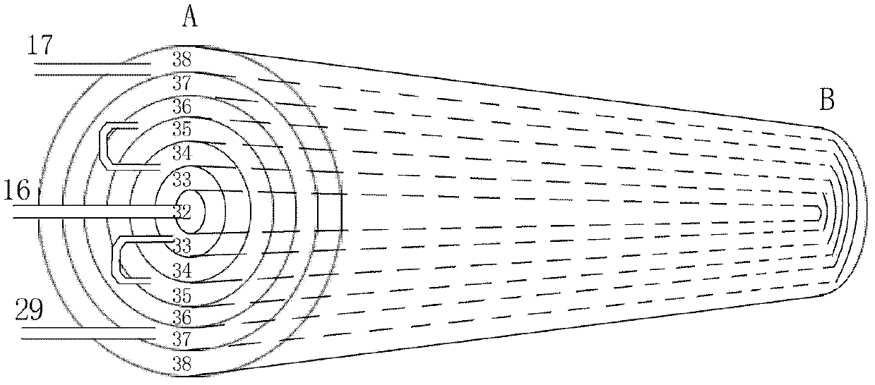
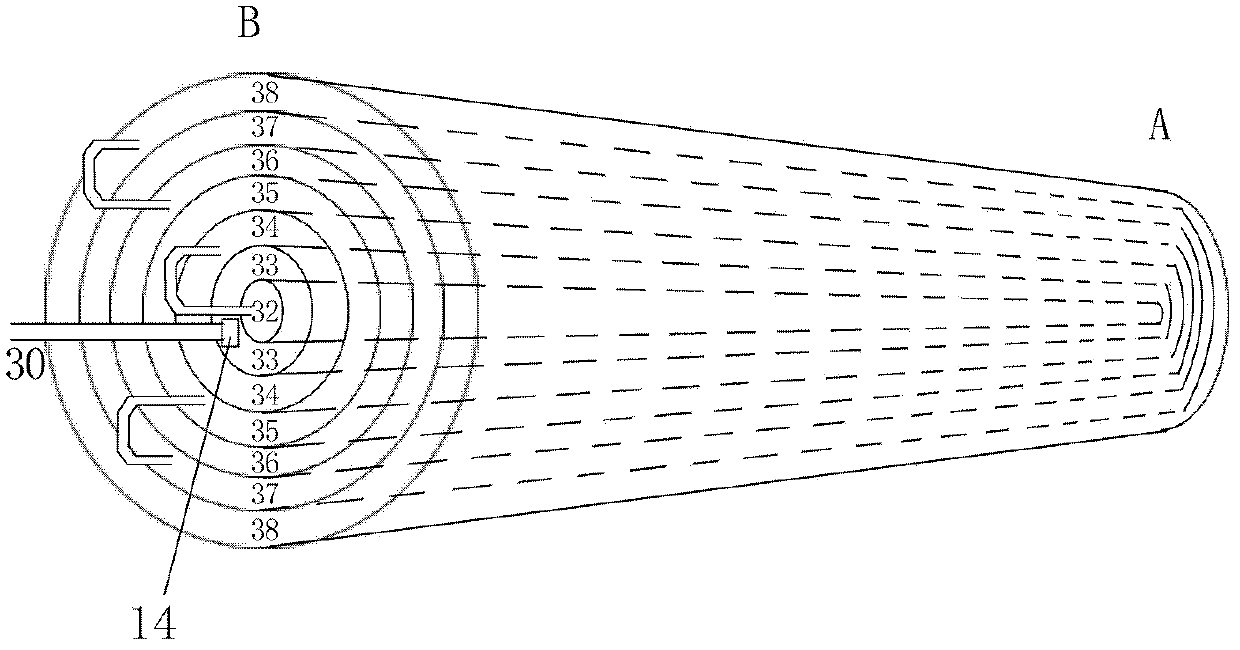
Disclosed is a heat-radiating internal-circulation power generation device, comprising a solar energy tube (5), three high-positioned expansion reservoirs (6-1, 6-2, 6-3), a low-positioned oil storage reservoir (25), three circulation pumps (8-1, 8-2, 8-3), an energy storage tank (7), a constant temperature furnace (12), a condensed water expansion tank (10), a high pressure plunger pump (13), a high pressure atomizing device (14), a steam generator (15), a steam storage tank (18), a steam turbine (19), a power generator (20), a circulating steam duct (21), a steam condenser (22) and a condensed water pipe (23). In the energy storage tank (7), a saline solution is used as an energy storage medium. Complementary heating of heat conductive oil with other multiple energy sources and solar energy is achieved by the constant temperature furnace (12). The steam generator (15) has layers of annular sealing ducts and the heat conductive oil circulated within the system conducts heat to the steam generator (15), such that an atomized moisture flow is instantly converted into high temperature and high pressure steam to arrive at a critical effect. The present device has the advantages of a long service life and easy maintenance, and is applicable in the fields of large-, middle- and small-scale power generation.
Description
technical field [0001] The invention relates to a power generation device, in particular to a thermal radiation internal circulation power generation device. Background technique [0002] The invention improves and upgrades the steam generator in the original solar oil heat conduction heat supply device. The saline solution is contained in the energy storage tank, which has the advantages of high boiling point and low cost; the constant temperature tank is improved into a constant temperature furnace, which has the advantage that various energy sources (fossil energy, bioenergy, gas, fuel oil, etc.) can be used to heat the heat transfer oil. At present, power generation devices on the market mainly use single thermal power, single hydraulic power, single solar power, and single nuclear energy to generate electricity. Their models are traditionally outdated, with low heat conversion efficiency and easy loss of heat energy, resulting in energy waste. Contents of the inventio...
Claims
Application Information
Patent Timeline
Application Date:The date an application was filed.
Publication Date:The date a patent or application was officially published.
First Publication Date:The earliest publication date of a patent with the same application number.
Issue Date:Publication date of the patent grant document.
PCT Entry Date:The Entry date of PCT National Phase.
Estimated Expiry Date:The statutory expiry date of a patent right according to the Patent Law, and it is the longest term of protection that the patent right can achieve without the termination of the patent right due to other reasons(Term extension factor has been taken into account ).
Invalid Date:Actual expiry date is based on effective date or publication date of legal transaction data of invalid patent.