Multi-stage utilization system for transferring exhaust afterheat energy of power station boiler

An energy transfer, power station boiler technology, applied in preheating, feed water heaters, lighting and heating equipment, etc., can solve the problems of limited increase in flue gas temperature, limited increase in air temperature, loss of cold source, etc.

Inactive Publication Date: 2012-07-25
JINAN DANENG POWER TECH
View PDF4 Cites 15 Cited by
  • Summary
  • Abstract
  • Description
  • Claims
  • Application Information

AI Technical Summary

Problems solved by technology

In fact, although this method can improve the energy level of waste heat, it obviously has the following disadvantages: (1) The flue gas still passes through the heat exchange of the air preheater first, and the increase of the flue gas temperature is limited, which makes the improvement of the energy level of waste heat Limited; (2) After passing through the high-level flue gas heat exchanger, there is a second-stage flue gas heat exchanger for heating the air. Obviously, the flue gas temperature of this stage heat exchanger is very low, and the air temperature increases (3) The flue gas temperature at the outlet of the last-stage flue gas heat exchanger is at an extremely low level, and low-temperature corrosion will inevitably occur, which greatly affects the reliability of the system
Although the energy level of waste heat recovery has been increased, this part of the energy level enters the steam turbine, and the efficiency is improved by squeezing out the steam extraction of the steam turbine, and this part of the exhausted steam extraction in the steam turbine will cause a loss of cold source
Therefore, from the perspective of economic benefits, this system is not cost-effective

Method used


Image

  • Multi-stage utilization system for transferring exhaust afterheat energy of power station boiler
  • Multi-stage utilization system for transferring exhaust afterheat energy of power station boiler

Examples


Embodiment Construction

[0034] The best embodiment of the present invention is illustrated below in conjunction with accompanying drawing:

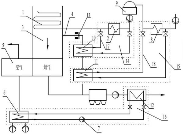
[0035]When the present invention works, the low-temperature flue gas flowing out from the air preheater 5 enters the third-stage flue gas cooler 12 to release heat and reduce the outlet temperature of the flue gas. This part of the flue gas waste heat is used to heat the independent circulating medium of the third-stage flue gas cooler. After its temperature is increased, it enters the boiler heater 6 to heat the cold air entering the air preheater 5, so that the air entering the air preheater 5 The cold air temperature increases. Adjust the flue gas regulator 13 to gradually increase the amount of flue gas passing through the bypass flue 4, and this part of high-temperature flue gas flows through the first-stage flue gas cooler 10 and the second-stage flue gas cooler 11 in sequence to release heat. The temperature of the flue gas at the outlet decreases, and f...


PUM


Abstract

The invention provides a multi-stage utilization system for transferring exhaust afterheat energy of a power station boiler. The key technology of the multi-stage utilization system is that: a bypass flue is added between a main economizer and an air pre-heater on a main flue of a boiler; a two-stage smoke cooler is arranged on the bypass flue to form a high-energy-level smoke afterheat utilization sub-system and a middle-energy-level smoke afterheat utilization sub-system, and a third-stage smoke cooler is arranged behind the air pre-heater to form a low-energy-level smoke afterheat utilization sub-system. Afterheat energy transferring and utilization are achieved by smoke flow adjusting devices of the arranged main flue and the bypass flue. The energy-saving effect is improved at the maximal degree, so that the benefit generated by the exhaust afterheat is maximized.

Description

technical field [0001] The invention belongs to a thermal power plant boiler exhaust heat energy recovery system, in particular to a thermal system that uses a combination of multi-stage flue gas coolers to transfer low-level energy from boiler exhaust heat and improve energy levels for multi-level utilization . Background technique [0002] The design value of the exhaust gas temperature of the power plant boiler is 110°C-130°C, and the actual operating temperature is mostly higher than the design value, and some boilers can even be as high as 160°C. Therefore, there is a large amount of waste heat of flue gas in the exhaust gas at the tail of the boiler. At present, many methods of recovering flue gas waste heat have been adopted in engineering, and there are also many patents related to the recovery of flue gas waste heat of boilers. [0003] Patent No. 200620088594 "Boiler Low-Pressure Economizer", by installing a low-pressure economizer in the flue behind the air preh...

Claims


Application Information

Patent Timeline
Patent Type & Authority Applications(China)
IPC IPC(8): F22D1/36F22D11/00
Inventor 孙奉仲史月涛陆万鹏
Owner JINAN DANENG POWER TECH
Why Eureka
Try Eureka