Air pre-heater system preventing low-temperature corrosion and air pre-heating method

An air preheater and air preheating technology, applied in combustion methods, lighting and heating equipment, indirect carbon dioxide emission reduction, etc., can solve problems such as vacuum damage in the pipe, damage to the air preheater, and inability to transfer latent heat of steam. Achieve the effect of prolonging service life, preventing low temperature corrosion and avoiding damage

Active Publication Date: 2012-08-01
BIHAIZHOU BEIJING ENERGY SAVING EQUIP CO LTD
View PDF5 Cites 7 Cited by
  • Summary
  • Abstract
  • Description
  • Claims
  • Application Information

AI Technical Summary

Problems solved by technology

[0015] 1. The commonly used tube box type air preheater has a low temperature of the air to be heated, sometimes even lower than the dew point temperature of the sulfur-containing flue gas, so that the side tube wall of the flue gas is easily damaged due to low-temperature corrosion, resulting in shutdown Furnace maintenance, and even the scrapping of the air preheater;
[0016] 2. In the long-term operation of the heat-pipe air preheater, the air is easily sucked into the heat exchange tube and the vacuum degree in the tube is destroyed, so that the latent heat of the vaporized steam in the tube cannot be transferred to the tube wall, and the air cannot be continued to be heated. Problems causing this heat pipe air preheater to fail;
[0017] 3. The use of ND steel pipe type air preheater is easy to increase the manufacturing cost, and low temperature dew point corrosion will also occur after a long running time, resulting in damage to the air preheater;
[0018] 4. In practical application, the enamel tube air preheater is prone to uneven thickness of the coating, and the coating of the pipe is easily damaged after welding, resulting in the problem of low-temperature dew point corrosion and damage after a short period of actual online operation;

Method used


Image

  • Air pre-heater system preventing low-temperature corrosion and air pre-heating method
  • Air pre-heater system preventing low-temperature corrosion and air pre-heating method

Examples


Embodiment Construction

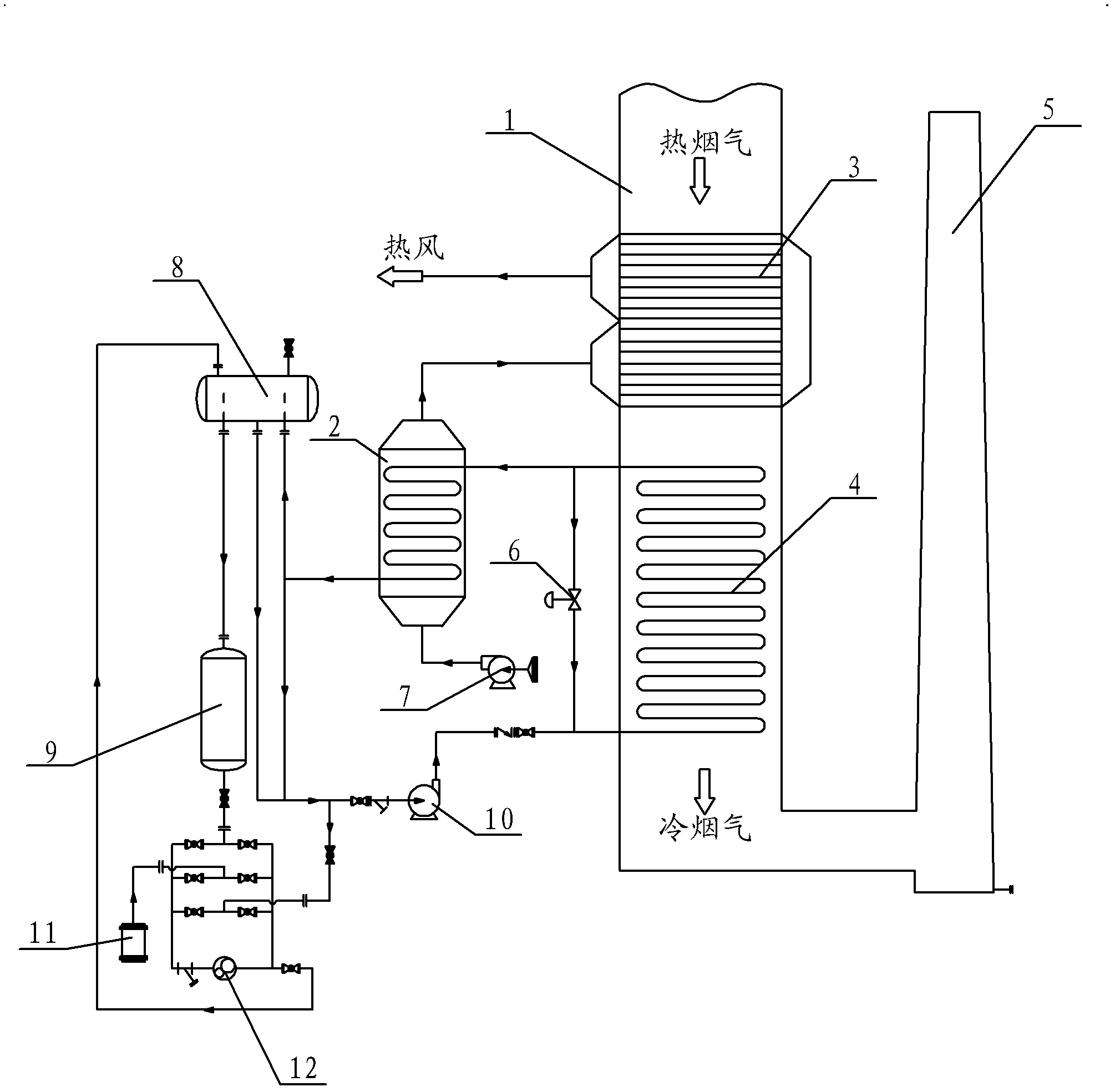
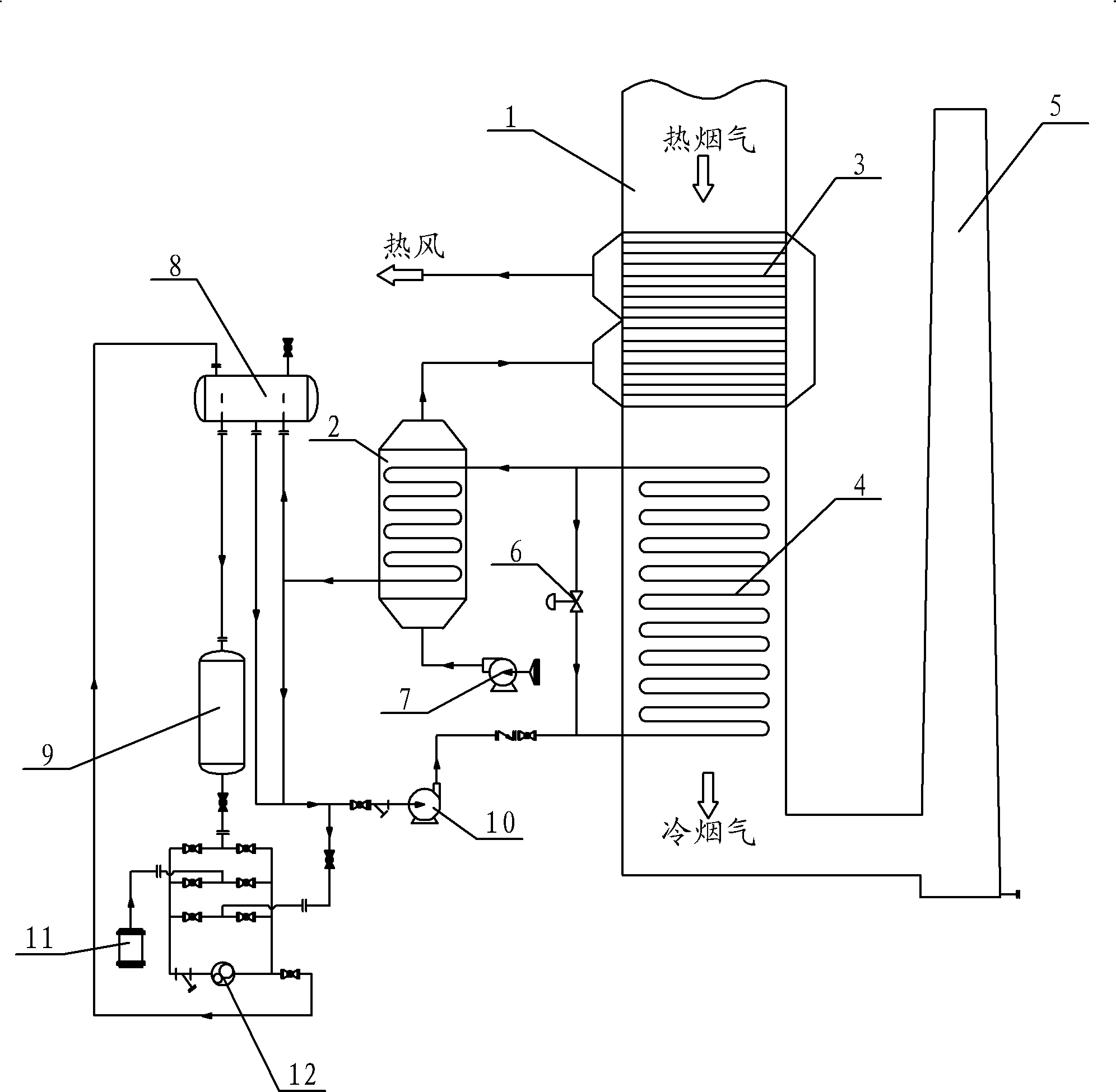
[0041] Such as figure 1 As shown, a low-temperature corrosion-resistant air preheater system according to the present invention includes a heat exchange system and a heat medium system;

[0042] The heat exchange system includes flue gas-air heat exchanger 3, flue gas-heat medium heat exchanger 4, heat medium-air heat exchanger 2, flue gas-air heat exchanger 3, flue gas-heat medium heat exchanger 4 Installed in the flue 1 of the heating furnace, and arranged in sequence along the flue gas flow direction, the heat medium-air heat exchanger 2 is arranged outside the flue 1 of the heating furnace;

[0043] The inlet of the flue gas-heat medium heat exchanger 4 is connected to the output end of the centrifugal pump 10, the outlet of the flue gas-heat medium heat exchanger 4 is connected to the heat medium inlet of the heat medium-air heat exchanger 2, and the heat medium-air heat exchanger The heat medium outlet of 2 is connected to the input end of the centrifugal pump 10;

[0...


PUM


Abstract

Provided are an air pre-heater system preventing low-temperature corrosion and an air pre-heating method. The air pre-heater system comprises a heat exchange system and a heating medium system. The heat exchange system comprises a smoke-air heat exchanger, a smoke-heating medium heat exchanger and a heating medium-air heat exchanger. The smoke-air heat exchanger and the smoke-heating medium heat exchanger are sequentially arranged in a heating furnace flue along the smoke flowing direction, and the heating medium-air heat exchanger is arranged outside the heating furnace flue. The smoke-heating medium heat exchanger, the heating medium-air heat exchanger and a heating medium system are connected in series to form a circulating system, smoke heat is transferred to a heating medium through the smoke-heating medium heat exchanger, an air inlet of the heating medium-air heat exchanger is connected with a fan, and outside air is subjected to primary heating of the heating medium-air heat exchanger, then enters the smoke-air heat exchanger to enable the air temperature to be higher than the dew-point temperature of sulfur-containing smoke and is used for supporting combustion after being subjected to secondary heating of high-temperature smoke. The phenomenon of low-temperature corrosion can be prevented, and accordingly an air pre-heater can run on line for a long period.

Description

technical field [0001] The invention relates to heat exchange equipment for a heating furnace waste heat recovery system, in particular to an air preheater system and a corresponding air preheating method for recycling waste heat in flue gas and preventing low-temperature corrosion. Background technique [0002] The air preheater is a heat exchange device that uses the heat of the flue gas at the tail of the boiler to heat the air required for fuel combustion to improve the thermal efficiency of the boiler. Generally referred to as an air preheater, it can be divided into two types: tube box type and rotary type; the working principle of the tube box preheater is relatively simple, the flue gas flows through the outside of the tube box, the air passes through the inside of the tube box, and heat is transferred through different temperature differences , same principle as economizer, superheater, etc. [0003] The working principle of the rotary preheater is: the rotor part ...

Claims


Application Information

Patent Timeline
Patent Type & Authority Applications(China)
IPC IPC(8): F23L15/00
CPCY02E20/34
Inventor 孟庆
Owner BIHAIZHOU BEIJING ENERGY SAVING EQUIP CO LTD
Why Eureka
Try Eureka