Immersion control device for lithography machine

A technology of control device and lithography machine, applied in the direction of photolithography exposure device, micro-lithography exposure equipment, etc., can solve the problems of pressure concentration, uneven air flow, and affecting imaging quality, so as to relieve pressure accumulation and pressure distribution Uniform, low-scattering effects

Inactive Publication Date: 2013-12-04
INST OF OPTICS & ELECTRONICS - CHINESE ACAD OF SCI
View PDF4 Cites 0 Cited by
  • Summary
  • Abstract
  • Description
  • Claims
  • Application Information

AI Technical Summary

Problems solved by technology

However, in the various airtight structures proposed, there are the following problems: (1) The phenomenon of uneven flow and pressure concentration at the boundary of the airtight seal
Uneven air flow is not conducive to liquid sealing on the one hand, and causes leakage during stepping and scanning. On the other hand, it may cause cracking of the gap flow liquid film, causing air bubbles to enter the exposure field between the projection lens and the silicon wafer, thereby affecting imaging. quality
(2) When the liquid injection and recovery rates are unbalanced, the accumulated liquid will exert a force on the projection objective lens, and the joint action of these normal forces and shear stress will be transmitted to the last lens of the projection objective lens, which will cause unnecessary damage to the projection objective lens system. vibration

Method used


Image

  • Immersion control device for lithography machine
  • Immersion control device for lithography machine
  • Immersion control device for lithography machine

Examples


Embodiment Construction

[0019] In order to make the purpose, technical solution and advantages of the present invention more clear, the working principle, structure and specific implementation of the present invention will be further introduced below in conjunction with the accompanying drawings.

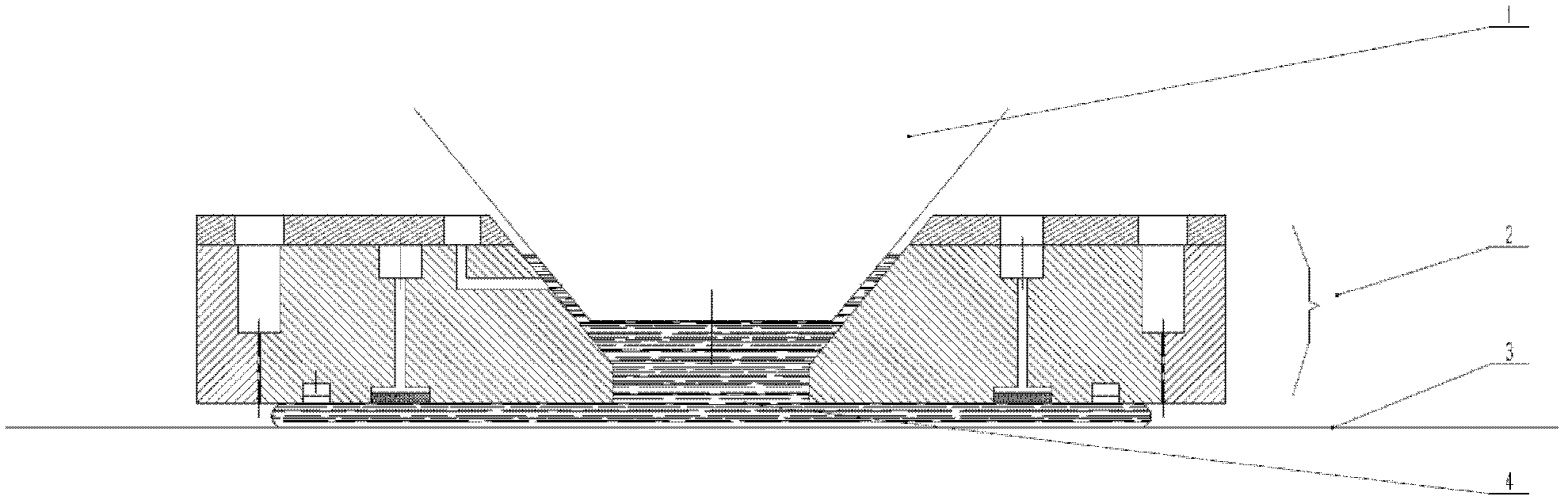
[0020] Such as figure 1 As shown, the assembly of the immersion control device and the end element of the projection lens group according to the embodiment of the present invention is shown. The device can be applied in step-and-repeat or step-and-scan lithography equipment. During the exposure process, the light emitted from the light source, such as: ArF or F2 excimer laser, passes through the aligned mask plate, the end element 1 of the projection lens group and the lens-silicon wafer gap field filled with immersion liquid 4, to the silicon The photoresist on the surface of sheet 3 is exposed.

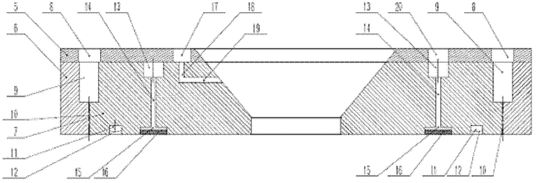
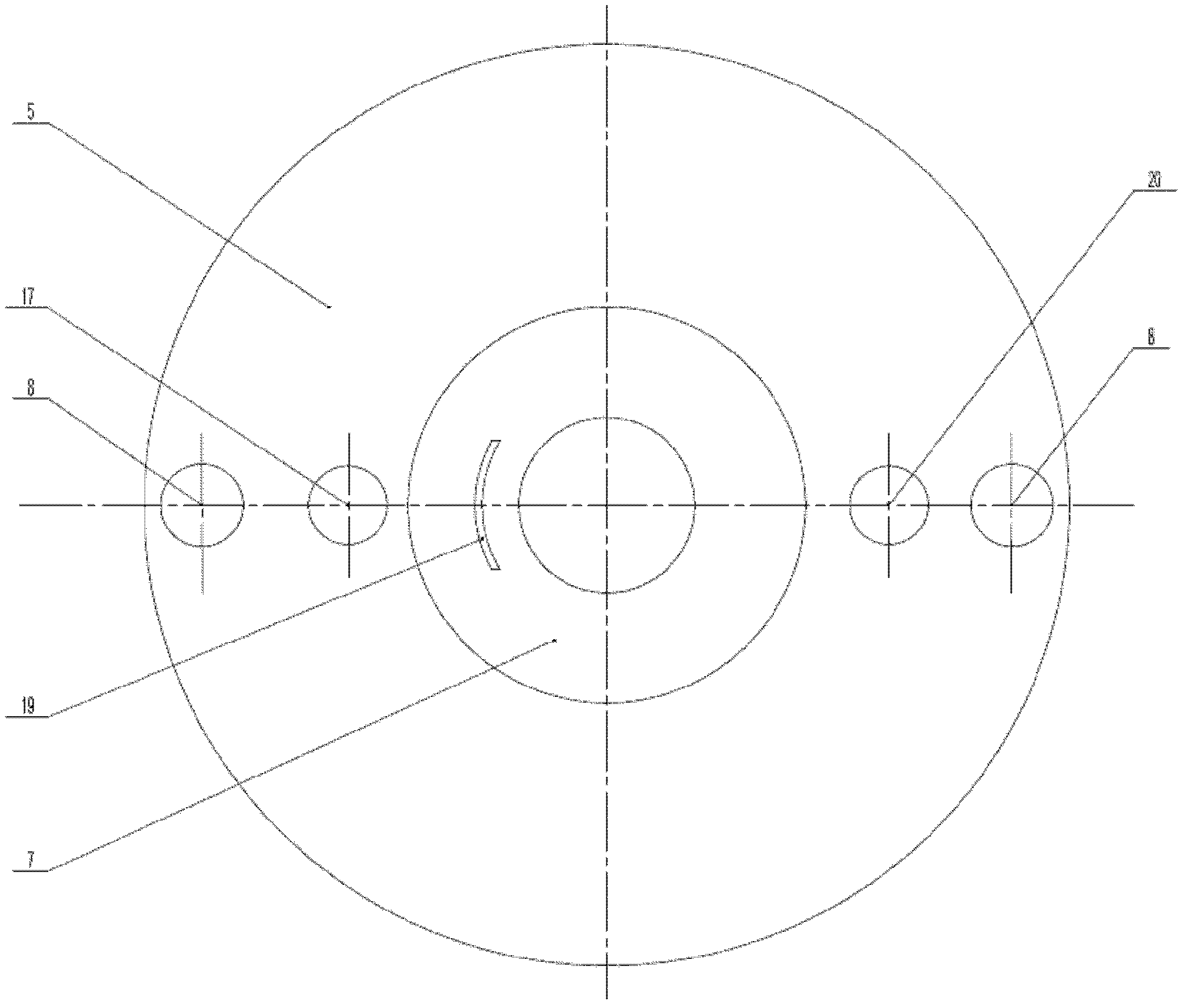
[0021] Such as figure 2 , image 3 , Figure 4 It shows an immersion control device 2 provided between t...


PUM


Abstract

The invention provides an immersion control device for a lithography machine, which is arranged between a projecting lens group tail end element and a silicon chip. The immersion control device comprises a cover plate, an outer component and an inner component, wherein the cover plate is an annular plate and is provided with a liquid inlet, a liquid outlet and an air inlet sequentially along a radial direction from the center to the outside, the outer component is an annular plate in a step shape, the inner component is an annular plate with a step-shaped outer side, the inner side of the inner component is in a cone shape which is matched with the shape of the projecting lens group tail end element, a liquid outlet lower ring groove and a ring-shaped pressure balanced groove are sequentially arranged on the lower portion of the inner component outwards along a radial direction, a fan-shaped groove, a liquid inlet hole and a liquid outlet upper ring groove are sequentially arranged on the upper portion of the inner component outwards along the radial direction, and the liquid outlet upper ring groove and the liquid outlet lower ring groove are connected through uniformly distributed through holes. By means of the immersion control device for the lithography machine, liquids can be conveyed in gaps between the projecting lens group tail end element and the silicon chip, and no leakage liquid conveying and sealing control are guaranteed.

Description

technical field [0001] The present invention relates to the technical field of the sealing control device for liquid supply and recovery in the immersion lithography system, in particular to an immersion control device for a lithography machine, which is located between the end element of the projection lens group and the silicon wafer The liquid is transported in the gap, and the liquid transmission and sealing control device that ensures that the liquid does not leak. Background technique [0002] According to the traditional lithography route, to improve the lithography resolution of the exposure system, the exposure wavelength can be reduced or the numerical aperture of the projected object image can be increased. Experimental studies have shown that reducing the exposure wavelength is not only long-term and costly, but also poses a great challenge to lens materials and photoresist materials with shorter wavelength bands. Increasing the numerical aperture can effectivel...

Claims


Application Information

Patent Timeline
Patent Type & Authority Patents(China)
IPC IPC(8): G03F7/20
Inventor 李金龙胡松赵立新李兰兰盛壮
Owner INST OF OPTICS & ELECTRONICS - CHINESE ACAD OF SCI
Why Eureka
Try Eureka