

Improved electroconductive glass fiber reinforced plastic electric demister
A conductive glass fiber reinforced plastic and electric mist eliminator technology, applied in the direction of external electrostatic separator, electrode structure, electrostatic separation, etc., can solve the problems of affecting the defogging efficiency, large creep, lead poisoning, etc., to improve the defogging efficiency, Shake reduction effect
- Summary
- Abstract
- Description
- Claims
- Application Information
AI Technical Summary
Problems solved by technology
Method used
Image

Examples
Embodiment Construction
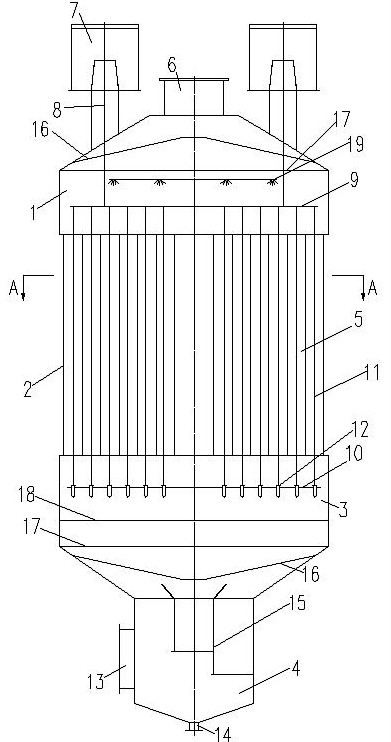
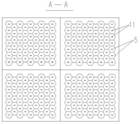
[0025] An improved conductive FRP electrostatic demister, including a shell, which is composed of an upper shell 1, a dust collecting pole chamber 2, a middle shell 3, and a lower shell 4 from top to bottom. The bottom of the upper and middle housings 3 is in the shape of a prism, and the top of the upper housing 1 is provided with an air outlet flange 6, and the upper housing 1 on both sides of the air outlet flange 6 is respectively provided with an insulating insulation box 7, which is insulated. The incubator 7 is provided with a cathode hanger 8, and the cathode hanger 8 is connected to the upper cathode carrying frame 9 in the upper casing 1; the lower cathode carrying frame 10 is arranged in the middle casing 3, and the dust collecting The pole chamber 2 is a tube bundle group formed by a number of anode tubes 5 closely arranged through the shared surface. A cathode line 11 is passed through the center of each anode tube 5. The upper end of each cathode line 11 is laid o...
PUM
| Property | Measurement | Unit |
|---|---|---|
| Length | aaaaa | aaaaa |
| Inscribed circle diameter | aaaaa | aaaaa |
Abstract
Description
Claims
Application Information