Pulsating heat pipe heat-expanding plate and manufacturing method thereof
A technology of pulsating heat pipes and manufacturing methods, applied in indirect heat exchangers, lighting and heating equipment, cooling/ventilation/heating transformation, etc., can solve problems affecting system reliability, component performance degradation, and inability to work stably, and achieve high The effect of heat transfer, low cost and simple structure
- Summary
- Abstract
- Description
- Claims
- Application Information
AI Technical Summary
Problems solved by technology
Method used
Image

Examples
Embodiment 1
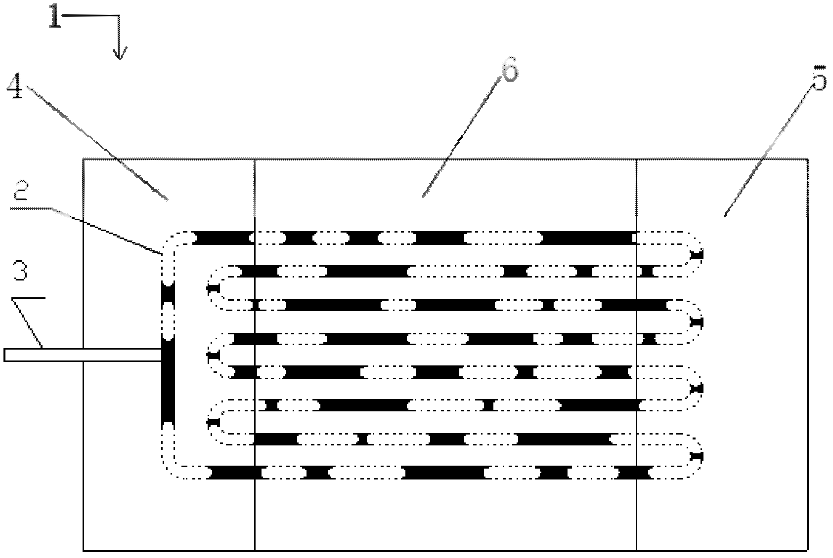
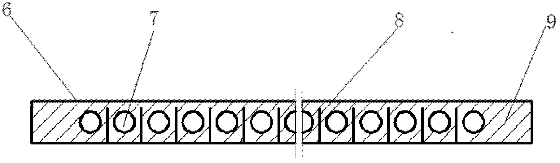
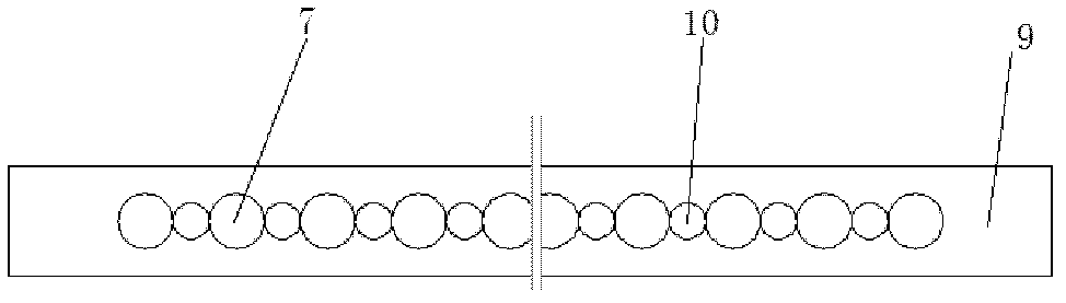
[0035] Such as Figures 1 to 6 As shown, the pulsating heat pipe expansion plate 1 includes a base plate 9, a front plug 11, a rear plug 12, and cover plates 4, 5, and 6, and the designed size of the heat expansion plate is 60×260×3mm 3 , the pulsating heat pipe heat expansion plate is produced in the following order: 1) Select a thicker plate, such as 8mm or 5mm, as the substrate 9, the substrate 9 is an oxygen-free copper plate or an L2 aluminum plate, and the substrate 9 is processed by wire cutting. A plurality of parallel capillary channels 7, then cut a slit 8 on the substrate between adjacent two capillary channels 7, but do not cut through, the depth of the slit 8 does not exceed the thickness of the substrate, the cross section of the heat expansion plate is as follows figure 2 As shown; 2) process several cylindrical protrusions 10 with a diameter of 1mm on the two ends of the substrate 9 connected to the front and rear plugs 11, 12, such as image 3 , 4 As shown,...
Embodiment 2
[0043] Such as figure 1 , 2 , 9, and 10, the size of the designed heat expansion plate is 60×260×3mm 3 , the pulsating heat pipe heat expansion plate 1 is produced in the following order: 1) select a relatively thick plate (such as 8mm or 5mm) as the base plate 9, the base plate is an oxygen-free copper plate or an L2 aluminum plate, and adopts the mode of wire cutting to process on this base plate. A plurality of parallel capillary channels 7, then cut a slit 8 on the substrate 9 between adjacent two capillary channels 7, but do not cut through, the depth of the slit 8 does not exceed the thickness of the substrate 9, and the heat expansion plate 1 cross section as figure 2 As shown; 2) The substrate 9 is gradually thinned to the target size, and then the upper cover plate 6 is welded on the side of the substrate 9 with the capillary channel 7 and the slit 8; 3) On the two ends of the substrate 9, respectively weld the strips There are front and rear plugs 11', 12' with e...
PUM
 Abstract
Description
Claims
Application Information
 - R&D
- Intellectual Property
- Life Sciences
- Materials
- Tech Scout
- Unparalleled Data Quality
- Higher Quality Content
- 60% Fewer Hallucinations
Browse by: Latest US Patents, China's latest patents, Technical Efficacy Thesaurus, Application Domain, Technology Topic, Popular Technical Reports.
© 2025 PatSnap. All rights reserved.Legal|Privacy policy|Modern Slavery Act Transparency Statement|Sitemap|About US| Contact US: help@patsnap.com