Process and equipment for converting carbon dioxide in flue gas into natural gas by using dump power energy

A technology of carbon dioxide and natural gas, applied in the field of natural gas, can solve problems such as grid-connected barriers for renewable energy power generation, difficulty in storing short-term surpluses, and environmental pollution caused by greenhouse gases in fossil energy power generation, achieving huge economic and social benefits, improving conversion efficiency, The effect of reducing pollution

Active Publication Date: 2012-09-12
WUHAN KAIDI ENG TECH RES INST CO LTD
View PDF3 Cites 36 Cited by
  • Summary
  • Abstract
  • Description
  • Claims
  • Application Information

AI Technical Summary

Problems solved by technology

[0008] The purpose of the present invention is to solve the problem of grid-connection obstacles in renewable energy power generation or the short-term surplus that is difficult to store, and the prob...

Method used


Image

  • Process and equipment for converting carbon dioxide in flue gas into natural gas by using dump power energy
  • Process and equipment for converting carbon dioxide in flue gas into natural gas by using dump power energy
  • Process and equipment for converting carbon dioxide in flue gas into natural gas by using dump power energy

Examples


Embodiment 1

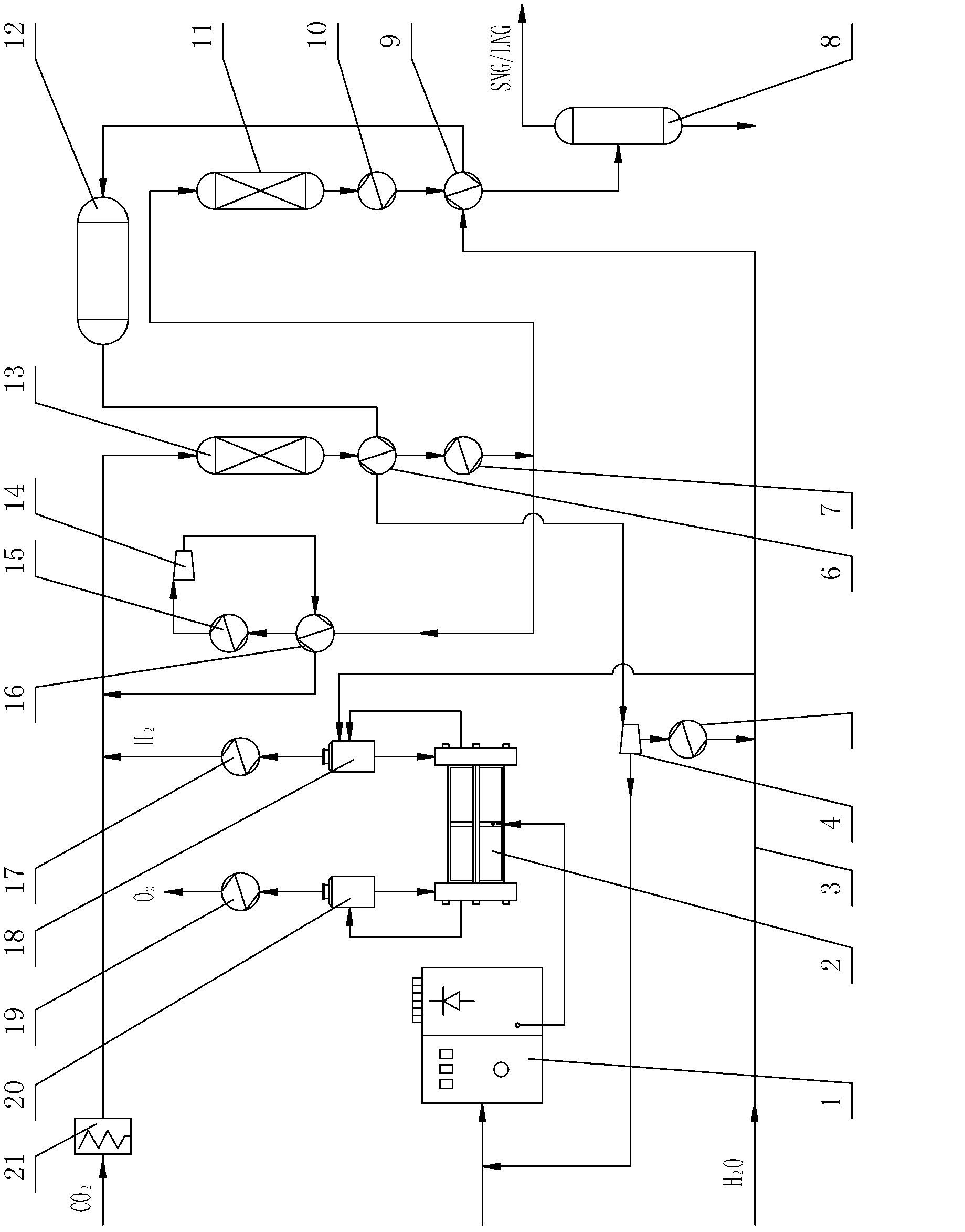
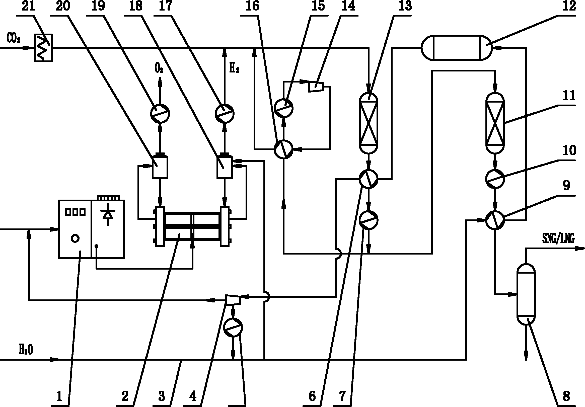
[0036] Embodiment 1: as figure 1 The shown equipment for converting carbon dioxide into natural gas by using excess electric energy is mainly composed of a voltage transformation and rectification device 1, an electrolytic cell 2, a turbo generator 4, a carbon dioxide heater 21, a first-stage fixed-bed reactor 13, and a second-stage fixed-bed reactor. The secondary fixed bed reactor 11, the natural gas condenser 8 and the process water pipeline 3 are composed of components. The output end of the transformer and rectifier device 1 is connected to the power interface of the electrolytic cell 2 . The anode gas-liquid outlet of the electrolytic cell 2 is connected with the gas-liquid input end of the oxygen separator 20, and the liquid output end of the oxygen separator 20 is connected with the anode liquid return port of the electrolytic cell 2, and the O of the oxygen separator 20 2 The output end links to each other with the inlet of oxygen cooler 19, and the outlet of oxygen ...

Embodiment 2

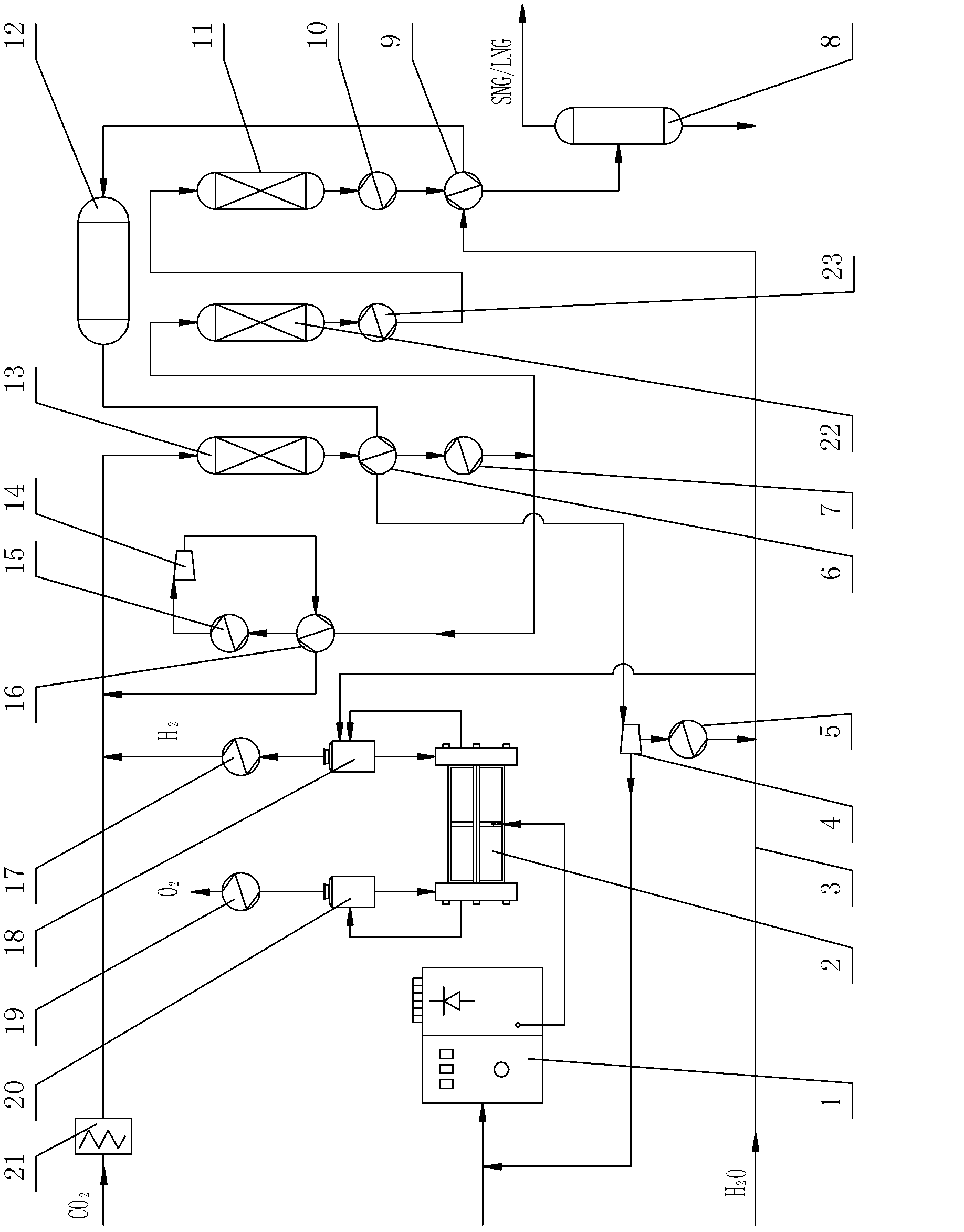
[0044] Embodiment 2: as figure 2 Another shown equipment for converting carbon dioxide into natural gas by using excess electric energy has the same structure and process flow as in Example 1, except that the first-stage fixed-bed reactor 13 and the second-stage fixed-bed reactor 11 are located between An intermediate fixed bed reactor 22 is also provided, the inlet of the intermediate fixed bed reactor 22 is connected with the mixed gas output end of the primary heat exchanger 7, and the outlet of the intermediate fixed bed reactor 22 is connected with the second stage through the intermediate heat exchanger 23. The inlets of the fixed bed reactor 11 are connected. In this way, a three-stage fixed-bed reactor is provided, and H can be distributed in three stages. 2 with CO 2The methanation reaction rate ensures complete reaction of raw materials. At the same time, the temperature at the inlet and outlet of the three-stage fixed-bed reactor can be lowered successively to o...


PUM


Abstract

The invention discloses a process and equipment for converting carbon dioxide in flue gas into natural gas by using dump power energy. According to the process, water is electrolyzed by using the dump power energy to generate hydrogen gas; the hydrogen gas and carbon dioxide captured from industrial flue gas are enabled to generate methanation reaction; meanwhile, water is heated by using the heat generated by the methanation reaction to generate superheated water vapor for driving a steam turbogenerator to generate power which is used for supplementing power energy for electrolyzing water, and thus natural gas which can be conveniently stored or conveyed is obtained by synthesizing. The equipment is mainly formed by combining a transforming and rectifying device, an electrolytic bath, a steam turbogenerator, a carbon dioxide heater, at least two-stage of fixed bed reactors, various indirect heat exchangers, a steam drum, a natural gas condenser and a process water pipeline. According to the process and equipment disclosed by the invention, the defects that internet obstacles exist or power is excessive in a short time and difficult to store in a mode of generating power by using renewable energy sources are effectively overcome, the problem that the environment is polluted by room temperature gases in a mode of generating power by using fossil energy is effectively solved and the renewable energy sources and carbon dioxide waste gas can be reasonably utilized.

Description

technical field [0001] The present invention relates to a technique for converting industrial flue gas into energy by using excess electric energy generated by renewable energy such as solar energy, water energy, and wind energy, and specifically refers to a process for converting carbon dioxide in flue gas into natural gas by utilizing excess electric energy and equipment. Background technique [0002] At present, more than 90% of the world's annual total energy consumption of more than 16 billion tons of standard coal is fossil energy such as coal, oil, and natural gas, and my country is no exception, which has brought about extremely huge carbon dioxide emissions. Since the beginning of the 21st century, one of the greatest challenges facing mankind is the greenhouse effect caused by the massive emission of carbon dioxide, which has caused global warming, climate change, and global impacts on ecology, economy, and society. Environmental issues. In 2010, global carbon di...

Claims


Application Information

Patent Timeline
IPC IPC(8): C10L3/10C07C1/12C07C9/04C25B1/04C25B9/04C01B32/50
CPCC07C1/12Y02P20/133B01J7/00C10L3/08Y02E60/36C07C9/04C10L3/06C10L2290/06C10L2290/10C10L2290/38C10L2290/42C10L2290/54
Inventor 张岩丰陈义龙王志龙方章建郑兴才
Owner WUHAN KAIDI ENG TECH RES INST CO LTD
Why Eureka
Try Eureka