Disc cutter composite drill bit

A compound drill bit and disc cutter technology, which is applied in the direction of drill bits, drilling equipment, earthwork drilling and mining, etc., can solve the problems of bit mechanical penetration rate limitation, PDC teeth are difficult to penetrate rock, and cutting teeth have a small penetration depth, etc., to improve the impact The effect of rock breaking efficiency, avoiding adverse effects, and avoiding rapid wear

Inactive Publication Date: 2012-09-19
SOUTHWEST PETROLEUM UNIV
View PDF10 Cites 11 Cited by
  • Summary
  • Abstract
  • Description
  • Claims
  • Application Information

AI Technical Summary

Problems solved by technology

[0003] The tri-cone bit mainly breaks rocks in the form of crushing (the teeth are pressed into the rock to cause the rock to break), which is applicable to a wide range of formations, but the energy utilization rate is not high, and the rock breaking efficiency is relatively low.
Especially when drilling in deep formations, under the action of high-density drilling fluid, the cuttings holding effect at the bottom of the well is very obvious. It is difficult for the teeth to press into the formation and form effective fragmentation, and the mechanical penetration rate of the drill bit is greatly limited.
Low bearing life is one of the main factors restricting the service life of tricone bits
The tri-cone bit requires a large drilling pressure to ensure a high rock-breaking efficiency, so the load amplitude of the bearing is high. At the same time, the working principle of the teeth on the cone alternately breaking the rock will inevitably lead to axial or longitudinal vibration of the bit, and a relatively large amplitude. bearing load fluctuations
The main disadvantages of the PDC bit are: first, when the strength or hardness of the rock is high, it is difficult for the PDC teeth to eat into the rock to form effective scraping, especially when the PDC teeth are worn out, it is even more difficult for the teeth to enter the formation. The drilling speed of the drill bit will decrease sharply
Third, the wear rate of the PDC teeth on different radial areas of the PDC bit is significantly different. Generally, the wear rate of the cutting teeth in the outer area of ​​the drill bit (especially the outer 1 / 3 area of ​​​​the drill bit radius) is significantly faster than that of the teeth in the center area. Poor tooth wear balance, which reduces the overall performance of the drill bit
In the drilling of hard formations, the drilling efficiency of the drill bit is not high due to the small penetration depth of the cutting teeth

Method used


Image

  • Disc cutter composite drill bit
  • Disc cutter composite drill bit
  • Disc cutter composite drill bit

Examples


Embodiment 1

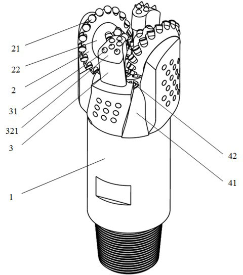
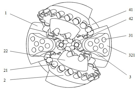
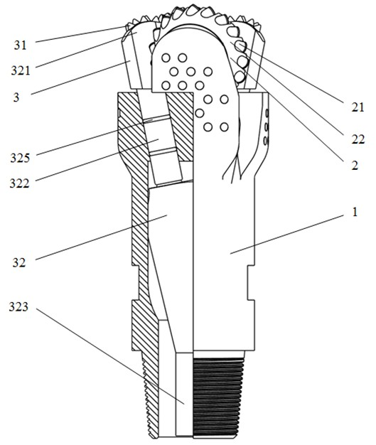
[0062] Such as Figure 1 to Figure 4 , Figure 7 , Figure 13 and Figure 19 As shown, a disc cutter composite drill bit includes a drill body 1. The drill body 1 is provided with a disc cutter cutting structure 2, an impact cutting structure 3 and a hydraulic structure composed of a flow channel 41 and a nozzle 42. The disc cutter cutting structure 2 includes There are disk cutter cutting teeth 21, and the impact cutting structure 3 includes a force transmission mechanism 32 for transmitting impact force and an impact cutting tooth 31. The force transmission mechanism 32 includes a punch 321, a dowel bar 322 and an anvil body 323, and the impact cutting tooth 31 is consolidated. On the punch 321 at the end of the force transmission mechanism 32, the punch 321 can slide relative to the drill body 1 in the impact force transmission direction. The composite drill bit does not include an impact mechanism, but has two runners, two sets of impact cutting units, and the runners 2...

Embodiment 2

[0064] This embodiment is basically the same as Embodiment 1, the difference being that an anvil body centralizing sleeve 324 ( Figure 5 shown), or directly process a surface on the anvil body 323 that forms a clearance fit with the inner hole of the drill body 1, so as to realize relative sliding and righting positioning between the anvil body and the drill body (such as Figure 6 shown).

Embodiment 3

[0066] This embodiment is basically the same as the above-mentioned embodiment, the difference is that there are two dowel bars in one or each impact cutting unit, and the motion rules of the two dowel bars are different, and there is relative motion between each other, wherein One dowel (one) 3221 is fixedly connected with the punch 321, the other dowel (two) 3222 is hinged with the anvil 323, and the two dowels are connected by a hinge (such as Figure 14 shown). When the punch 321 is far away from the center of the drill bit and the included angle between the impact direction and the axis of the drill bit is relatively large, it is easier to realize the conversion of the impact direction and the transmission of the impact force by using two dowel bars hinged to each other.


PUM


Abstract

The invention discloses a disc cutter composite drill bit belonging to the field of rock blasting tools for drilling equipment for oil and gas, mine engineering and building foundation engineering construction, geology, hydrology and the like. The disc cutter composite drill bit comprises a drill bit body and a disc cutter cutting structure arranged on the drill bit body; the drill bit body is also provided with an impact cutting structure; and the impact cutting structure comprises a force transferring mechanism for transferring impact force and impact cutting teeth, wherein the impact cutting teeth are solidified on a punch arranged at the tail end of the force transferring mechanism, and the punch can slide or slidingly impact relative to the drill bit body in the impact force transferring direction. Compared with a drill bit (also named as wheel type drill bit) with the disc cutter cutting structure, the disc cutter composite drill bit is not only beneficial to the drilling of the cutting teeth of the drill bit to stratums and the increment of the rock blasting efficiency, but also beneficial to the retardance of the wear rate of the cutting teeth and particularly has remarkable technical advantages for higher-strength and stronger-abrasiveness stratums which are difficult to drill.

Description

technical field [0001] The invention belongs to the field of rock-breaking tools used for drilling equipment such as petroleum and natural gas, mining engineering, building foundation engineering construction, geology, and hydrology. Background technique [0002] The drill bit is a rock-breaking tool used in drilling engineering to break rock and form a wellbore. Conventional drill bits used in drilling engineering today mainly include three-cone drill bits, polycrystalline diamond compact drill bits (ie, PDC drill bits) and punching drill bits (also known as rotary punching bits or drill bits). [0003] The tri-cone bit mainly breaks rock in the form of crushing (the teeth press into the rock to break the rock). It is applicable to a wide range of formations, but the energy utilization rate is not high, and the rock breaking efficiency is relatively low. Especially when drilling in deep formations, under the action of high-density drilling fluid, the cuttings holding effec...

Claims


Application Information

Patent Timeline
Patent Type & Authority Applications(China)
IPC IPC(8): E21B10/12E21B10/36E21B10/43E21B10/46
Inventor 杨迎新陈炼林敏石擎天包泽军张春亮
Owner SOUTHWEST PETROLEUM UNIV
Why Eureka
Try Eureka