
Resonant mode optical gyroscope signal detection device and method based on virtual instrument

A technology of signal detection and optical gyroscope, which is applied in the direction of Sagnac effect gyroscope, etc., can solve the problems that affect the research progress of resonant optical gyroscope, limit the accuracy of resonant optical gyroscope, program optimization and algorithm verification difficulties, etc., and achieve effective Conducive to gyroscope accuracy, shorten development time, and speed up research and development

Active Publication Date: 2012-09-19
BEIHANG UNIV
View PDF1 Cites 14 Cited by
  • Summary
  • Abstract
  • Description
  • Claims
  • Application Information

AI Technical Summary

Problems solved by technology

[0003] At present, the research on resonant optical gyroscope is still in the stage of laboratory research. The main reason is that various optical noise and circuit noise greatly limit the accuracy of resonant optical gyroscope.
On the basis of not changing the optical path, the accuracy of the resonant optical gyroscope can only be improved by changing the signal detection method and signal processing algorithm, while the traditional detection circuit has large noise, single function, long design cycle, and program optimization and algorithm verification are relatively difficult. Difficult, not conducive to the improvement of signal detection, seriously affecting the research progress of resonant optical gyroscope

Method used


Image

  • Resonant mode optical gyroscope signal detection device and method based on virtual instrument
  • Resonant mode optical gyroscope signal detection device and method based on virtual instrument
  • Resonant mode optical gyroscope signal detection device and method based on virtual instrument

Examples


Embodiment Construction

[0024] Below in conjunction with specific accompanying drawing, the present invention will be described in further detail

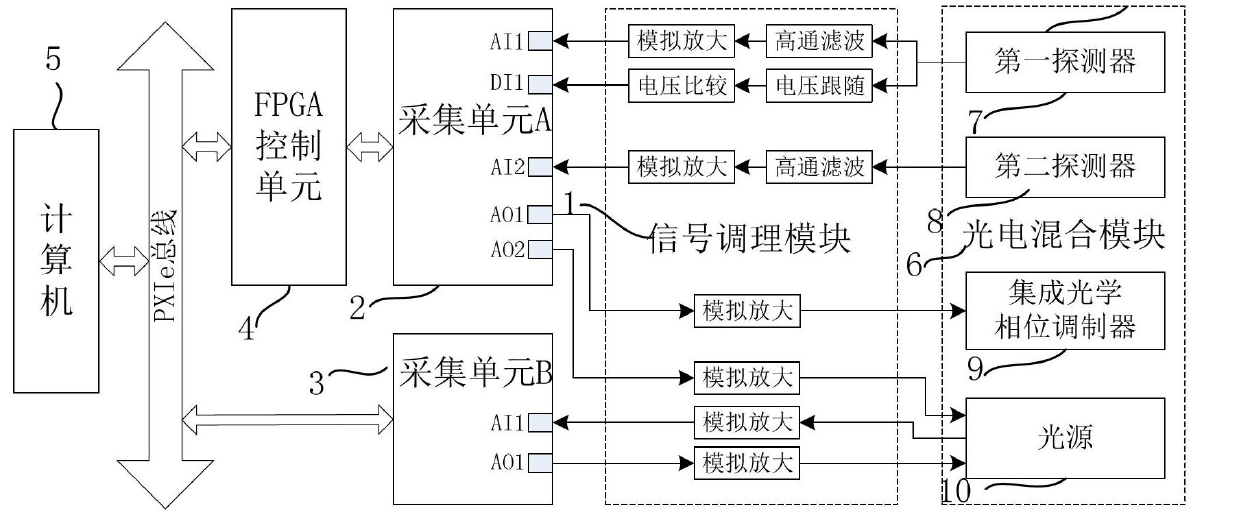
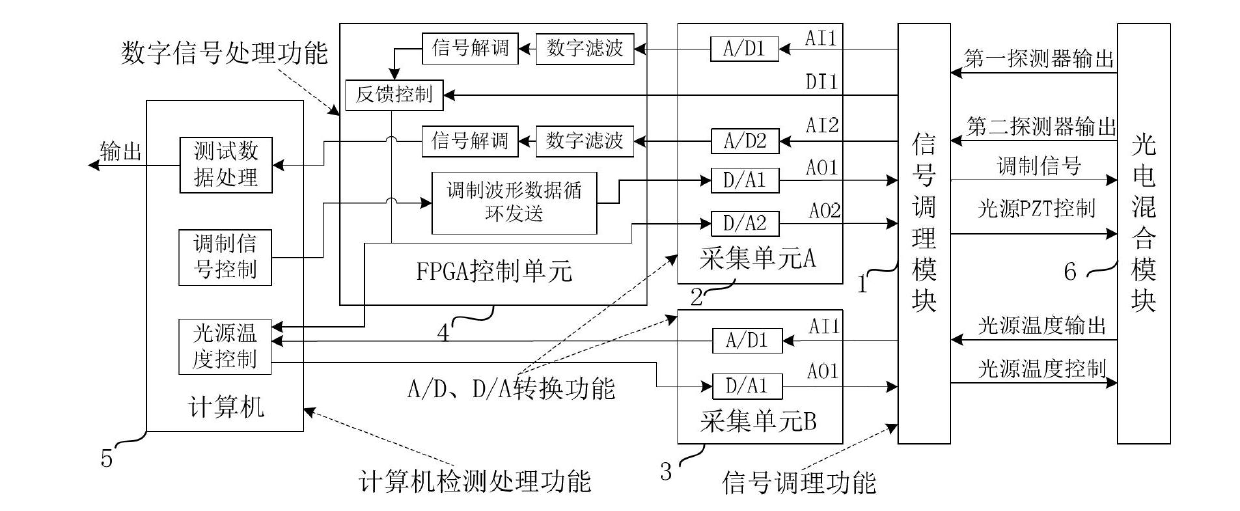
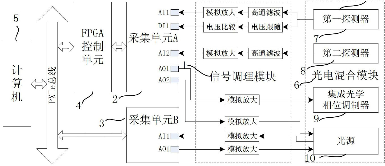
[0025] The present invention proposes a resonant optical gyro signal detection device based on a virtual instrument, such as figure 1 As shown, it consists of a signal conditioning module 1, an acquisition unit A2, an acquisition unit B3, an FPGA control unit 4 and a computer 5 based on the PXIe bus. The detection object of the present invention is the photoelectric hybrid module 6 , and the photoelectric hybrid module 6 includes a first detector 7 , a second detector 8 , an integrated optical phase modulator 9 and a light source 10 .

[0026] Described signal conditioning module 1 realizes the interface signal matching between photoelectric hybrid module 6 and acquisition unit A2, acquisition unit B3 by signal conditioning circuit, and it mainly comprises following four parts of conditioning circuit:

[0027] (1) On the one hand, the light intensity and...


PUM


Abstract

The invention provides a resonant mode optical gyroscope signal detection device and method based on a virtual instrument, belonging to the technical field of optical gyroscope signal detection. The resonant mode optical gyroscope signal detection device comprises a signal modulating module, a collection unit A, a collection unit B, an FPGA (Field Programmable Gate Array) control unit and a computer based on a PXIe (Pci Express-extensions-for-instrumentation) bus; an object to be detected is a photoelectric mixing module; and the photoelectric mixing module comprises a first detector, a second detector, an integrated optical phase modulator and a light source. According to the invention, modularized hardware of the virtual instrument is used for replacing a traditional detection circuit, hardware developing time is shortened, circuit noise is small, the anti-jamming capability is strong and the gyroscope precision is improved. Digital signal processing of a resonant mode optical gyroscope is carried out on FPGA programming based on labview virtual instrument software; and the verification of an algorithm can be rapidly carried out according to abundant resources in an FPGA and the flexibility of labview graphics programming, so as to accelerate a research speed of the resonant mode optical gyroscope.

Description

technical field [0001] The invention relates to the technical field of optical gyroscope signal detection, in particular to a resonant optical gyroscope signal detection technology based on a virtual instrument. Background technique [0002] The resonant optical gyroscope is a high-precision inertial angular velocity sensor based on the Sagnac effect. Because it is an all-solid-state structure device without moving parts, it has the advantages of small size, large dynamic range, high precision, short start-up time and long life. In recent years, it has received more and more attention and research. The resonant optical gyroscope obtains the angular velocity of the carrier by detecting the resonant frequency difference between the clockwise and counterclockwise light in the resonant cavity caused by the rotation. Due to the extremely weak Sagnac effect: when the ring length of the integrated optical ring resonant cavity is 12.8cm , when the working wavelength is 1550um, the ...

Claims


Application Information

Patent Timeline
IPC IPC(8): G01C19/72
Inventor 冯丽爽刘惠兰郅银周张仰成雷明粟妮
Owner BEIHANG UNIV
Learn More