Sludge dewatering device
A sludge dehydration and dewatering hole technology, which is applied in the direction of dehydration/drying/concentrated sludge treatment, can solve the problems of high energy consumption for water evaporation, low work efficiency, secondary pollution, etc., and achieve low-cost sludge treatment and increase High dehydration efficiency and dehydration degree
- Summary
- Abstract
- Description
- Claims
- Application Information
AI Technical Summary
Problems solved by technology
Method used
Image

Examples
Embodiment 1
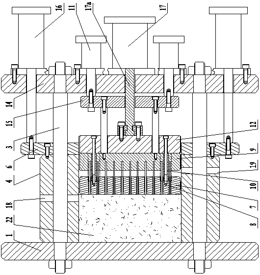
[0028] Such as figure 1 and Figure 8 As shown, this embodiment discloses a sludge dewatering device, which includes a cavity side wall 4, a movable plunger 7 that can reciprocate and slide in the cavity side wall 4, and a movable plunger driver 17. A set of dewatering holes 7c is provided; a mud pushing assembly for preventing the dewatering holes from being blocked is provided at the rear end of the movable plunger 7, and the rear end refers to the end of the movable plunger 7 that does not directly contact with the sludge. The mud pushing assembly includes a set of ejector rods 8, ejector rod fixing plates 9 and ejector rod drivers 11; each ejector rod 8 is located in the corresponding dewatering hole 7c, and the ejector rod fixing plate 9 is used to fix the ejector rods 8, And driven by the push rod driver 11, the push rod is driven to reciprocate in the dewatering hole. The movable plunger driver 17 and the ejector rod driver 11 can move separately according to their wo...
Embodiment 2
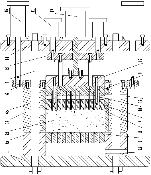
[0036] Such as figure 2 As shown, the difference between this embodiment and Embodiment 1 is that the cavity side wall 4 is divided into two parts: a fixed part 4a and a movable part 4b, and a fixed plunger 2 located opposite to the movable plunger is arranged in the fixed part 4a. , There is also a set of dehydration holes on the fixed plunger. One side of the movable part 4 b is provided with a water outlet hole 19 , and the movable part 4 b is connected to the cavity driver 16 through the cavity connecting plate 6 . Thus, the fixed plunger 2 is added as a dewatering part, which improves the dehydration efficiency. The dehydration hole of the fixed plunger can be set to correspond to the position of the dehydration hole of the movable plunger. The mud pushing assembly behind the movable plunger can be the same, yes The push rod extends into the dewatering hole of the fixed plunger, thereby realizing the dredging of the dewatering hole of the fixed plunger. Dividing the si...
Embodiment 3
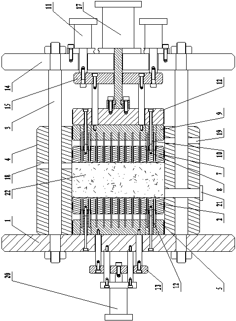
[0040] Such as image 3 As shown, the difference between this embodiment and Embodiment 1 is that the chamber driver 16 and the chamber connecting plate 6 in Embodiment 1 are omitted, and the structure of the fixed chamber side wall 4 is adopted. Further, a sludge discharge port and a sludge discharge valve 21 are provided on the side wall 4 of the cavity, and the treated sludge block 22 is taken out by opening the sludge discharge valve 21 .
[0041] Furthermore, in this embodiment, in the side wall 4 of the cavity, a fixed plunger 2 connected to the front fixed plate 1 is provided on the opposite side to the movable plunger, and a group of dehydration holes are also provided on the fixed plunger. After the plunger is fixed, a ejector rod fixing plate 5 is provided, and a group of ejector rods 12 corresponding to the dewatering holes of the fixed plunger are arranged on the ejector rod fixing plate 5, and the ejector rods 12 are located in the dehydration holes. The number o...
PUM
 Abstract
Description
Claims
Application Information
 - R&D
- Intellectual Property
- Life Sciences
- Materials
- Tech Scout
- Unparalleled Data Quality
- Higher Quality Content
- 60% Fewer Hallucinations
Browse by: Latest US Patents, China's latest patents, Technical Efficacy Thesaurus, Application Domain, Technology Topic, Popular Technical Reports.
© 2025 PatSnap. All rights reserved.Legal|Privacy policy|Modern Slavery Act Transparency Statement|Sitemap|About US| Contact US: help@patsnap.com