Liquid ammonia gasifying system and gasifying process thereof

A technology for liquid ammonia and ammonia gas, applied in fixed-capacity gas storage tanks, gas/liquid distribution and storage, pressure vessels, etc., can solve the increase in the cost of ammonia purification process, the limitations of the promotion and application of ammonia methods, and the limitations of the promotion and application of ammonia methods and other issues, to achieve the effect of novel system design, remarkable energy saving effect, energy saving and environmental protection of technological process

Active Publication Date: 2015-04-15
BEIJING ZHONGNENG NUOTAI ENERGY SAVING & ENVIRONMENTAL PROTECTION CO LTD
View PDF7 Cites 0 Cited by
  • Summary
  • Abstract
  • Description
  • Claims
  • Application Information

AI Technical Summary

Problems solved by technology

However, for applications requiring ammonia (NH 3 ) SCR denitrification and other processes generally consume a lot of energy, resulting in an increase in economic costs, which in turn leads to an increase in the cost of the entire ammonia purification process, thus limiting the promotion and application of the ammonia process
[0003] At present, there are two main methods to obtain gaseous ammonia: one is urea pyrolysis method, which uses electric heaters to provide heat through urea pyrolysis system to decompose urea into gaseous ammonia and carbon dioxide. This method starts from input of raw materials to pyrolysis reaction From generation to product separation, the process is complex and requires high system settings. At the same time, it also needs to consume a lot of materials and energy, and the economic cost is too high, which is not conducive to popularization and application; the other is to obtain gaseous ammonia through liquid ammonia gasification, mainly using The method of steam heating evaporates liquid ammonia into gaseous ammonia. Because the boiling point of liquid ammonia is -33.4°C, it is very easy to gasify. However, this method uses steam with high calorific value as a heat source, which inevitably causes a lot of waste of heat sources. Similarly, obtaining steam The heat source also requires energy consumption, thus causing an increase in economic costs and limiting the application of the ammonia method

Method used


Image

  • Liquid ammonia gasifying system and gasifying process thereof
  • Liquid ammonia gasifying system and gasifying process thereof
  • Liquid ammonia gasifying system and gasifying process thereof

Examples


Embodiment 1

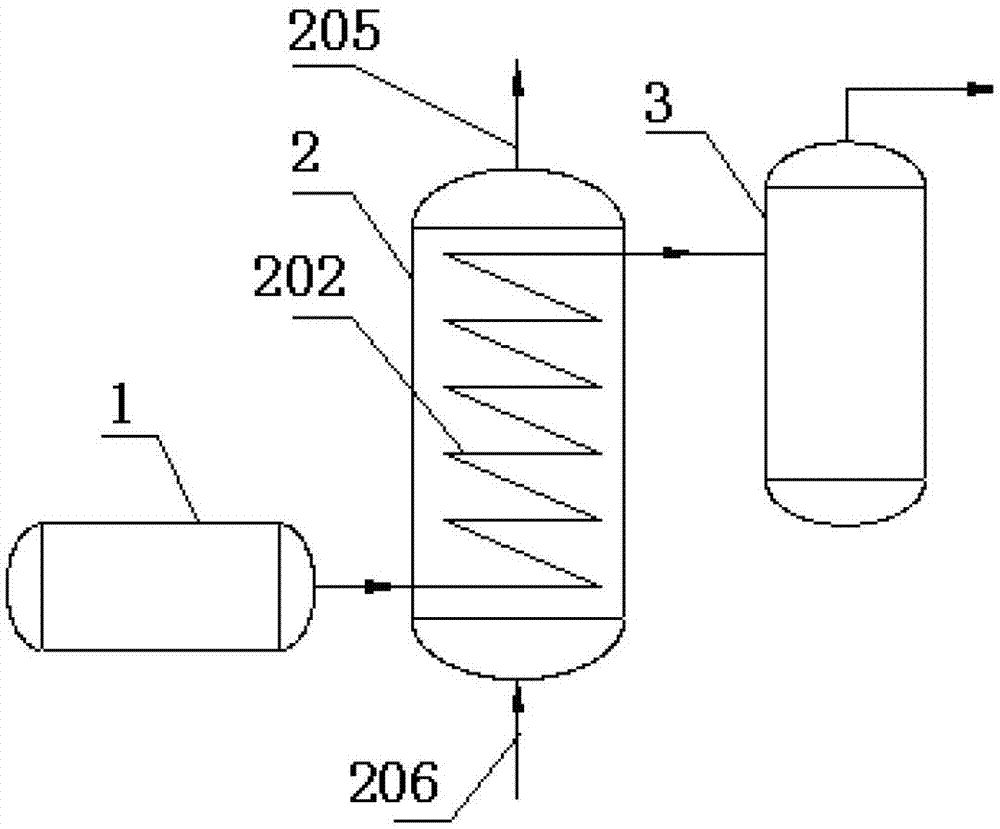
[0034] like figure 1 As shown, a liquid ammonia gasification system of the present invention includes a liquid ammonia delivery device 1 , a heat exchange device and a gas ammonia storage device 3 connected to each other, wherein the heat exchange device is a circulating water heat exchange device 2 .

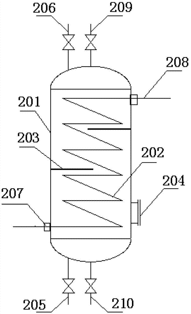
[0035] like figure 2 As shown, the circulating water heat exchange device 2 includes a casing 201, a heat exchange tube 202 arranged in the casing 201, three baffles 203 arranged at intervals in the casing 201, and an inspection port arranged at the lower part of the casing 201. 204. The circulating water input port 205 and the circulating water output port 206, the liquid ammonia input port 207 and the gas ammonia output port 208, the exhaust port 209 and the net discharge port 210 arranged on the housing 201; wherein the circulating water input port 205 is set At the bottom of the housing 201, the circulating water output port 206 is arranged on the top of the housing 201; ...

Embodiment 2

[0050] like figure 1 and figure 2 As shown, the setting and distribution of a liquid ammonia gasification system are the same as those in Example 1, wherein the difference is that: the heat exchange tubes are arranged side by side in parallel, that is, a tube-and-tube heat exchanger is used; the heat exchange tubes It is made of 16Mn alloy steel pipe; the number of said baffles is 4.

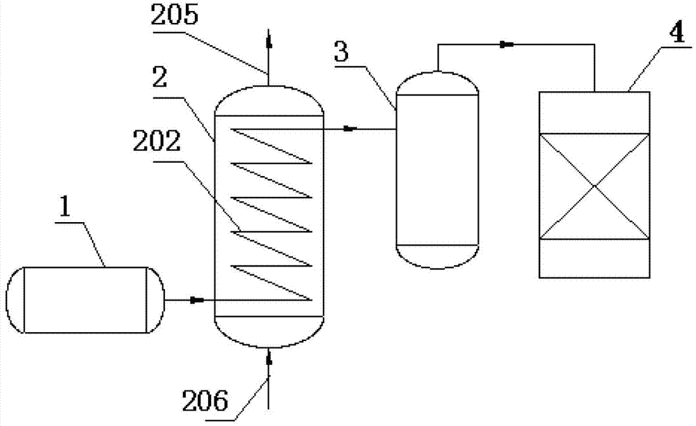
[0051] like image 3 As shown, taking the amount of gas ammonia of 380kg / h provided to the SCR denitrification process system of a coal-fired power plant as an example, the liquid ammonia gasification system of the present invention is used to gasify liquid ammonia, the same as in Example 1, except for the following steps:

[0052] In step (1), when the circulating water enters the heat exchange device 2 from the circulating water input port 205, the temperature at the inlet is 30°C;

[0053] In step (3), the flow rate of the circulating water used is 52.3m 3 / h.

[0054] Applying the pres...

Embodiment 3

[0056] like figure 1 and figure 2 As shown, the setting and distribution of a liquefied ammonia gasification system are the same as in Example 1, wherein the difference is that: the heat exchange tubes are arranged in parallel; the heat exchange tubes are made of 16Mn alloy steel pipes; The number of flow plates is 6.

[0057] like image 3 As shown, taking the amount of gas ammonia of 360kg / h provided to the SCR denitrification process system of a coal-fired power plant as an example, the liquid ammonia gasification system of the present invention is used to gasify liquid ammonia, the same as in Example 1, except for the following steps:

[0058] In step (1), when the circulating water enters the heat exchange device 2 from the circulating water input port 205, the temperature at the inlet is 32°C;

[0059] In step (3), the flow rate of the circulating water used is 45m 3 / h.

[0060] Applying the present invention to gasification of liquid ammonia, the cooling capacity...


PUM


Abstract

The invention relates to a liquid ammonia gasifying system and a gasifying process thereof, in particular to the liquid ammonia gasifying system applied to a selective catalytic reduction (SCR) denitration or ammonia desulphurization process and the gasifying process thereof. The liquid ammonia gasifying system comprises a liquid ammonia conveying device, a heat exchange device and a gas ammonia storage device which are connected with each other. The heat exchange device is a circulating water heat exchange device and comprises a casing, a heat exchange pipe arranged in the casing, a circulating water input port, a circulating water output port, a liquid ammonia input port and a gas ammonia output port, wherein the circulating water input port and the circulating water output port are arranged on the casing. In the process, circulating water is applied to gasify liquid ammonia. Compared with the prior art, the liquid ammonia gasifying system is optimized in design, simple in process flow, energy-saving and environment-friendly, the refrigeration performance of the liquid ammonia is fully utilized simultaneously when the required gas ammonia is obtained at low energy consumption and low investment, comprehensive utilization of energy is achieved, energy-saving effect is remarkable, utilized land is saved, economic cost is greatly reduced, and the liquid ammonia gasifying system is suitable for popularization and application in the fields of SCR denitration and the like where the gas ammonia needs applying.

Description

technical field [0001] The invention relates to a liquid ammonia gasification system and a gasification process thereof, in particular to a liquid ammonia gasification system and a gasification process applied in SCR denitrification or a desulfurization process using ammonia as a raw material. Background technique [0002] Sulfur and nitrogen oxides (SO 2 , NOx) pollutants, and the treatment technologies for these flue gas pollutants are relatively mature: limestone-gypsum method, ammonia method, double alkali method, selective catalytic reduction (SCR) method, selective non-catalytic reduction (SNCR) method, low-nitrogen combustion method, etc. Among them, the ammonia method is more respected because of its simple process flow and the efficient removal of sulfur and nitrogen pollutants in the flue gas without pollution. At the same time, the obtained ammonium salt product can also Make full use of it as a fertilizer source, correspondingly reduce investment costs and incre...

Claims


Application Information

Patent Timeline
Patent Type & Authority Patents(China)
IPC IPC(8): F17C7/04F28D7/08F28D7/16
Inventor 艾淑艳
Owner BEIJING ZHONGNENG NUOTAI ENERGY SAVING & ENVIRONMENTAL PROTECTION CO LTD
Why Eureka
Try Eureka