
Pulsed power supply based on superconductivity normal-conductivity combined pulse transformer

A technology of mixed pulse and pulse power, which is applied in the field of pulse power power supply, can solve the application requirements of unfavorable pulse power device miniaturization and light weight, affect the normal operation of the device, and complicate the control system. Low, simple control system effect

Inactive Publication Date: 2012-10-10
SOUTHWEST JIAOTONG UNIV
View PDF5 Cites 12 Cited by
  • Summary
  • Abstract
  • Description
  • Claims
  • Application Information

AI Technical Summary

Problems solved by technology

[0004] Most of the traditional superconducting energy storage pulse power supplies are uncoupled energy storage inductors in series charge and parallel discharge mode. The pulse output in this mode needs to be realized by a circuit breaker, but the moment the energy storage inductor discharges, a high amplitude will be generated at both ends of the circuit breaker. The voltage pulse of the value is easy to cause damage to the circuit breaker, thus affecting the normal operation of the entire device
In addition, if you want to obtain higher amplitude current pulses, you need to stack many energy storage inductor modules. The more modules, the larger the system scale and the more complex the control system, which is not conducive to the miniaturization and lightweight application requirements of pulse power devices.

Method used


Image

  • Pulsed power supply based on superconductivity normal-conductivity combined pulse transformer
  • Pulsed power supply based on superconductivity normal-conductivity combined pulse transformer
  • Pulsed power supply based on superconductivity normal-conductivity combined pulse transformer

Examples


Embodiment Construction

[0018] The present invention will be further described below in conjunction with drawings and embodiments.

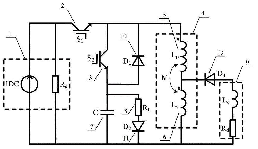
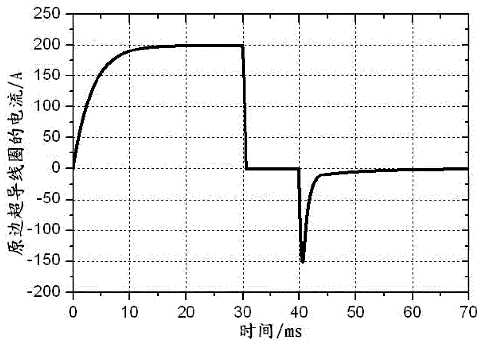
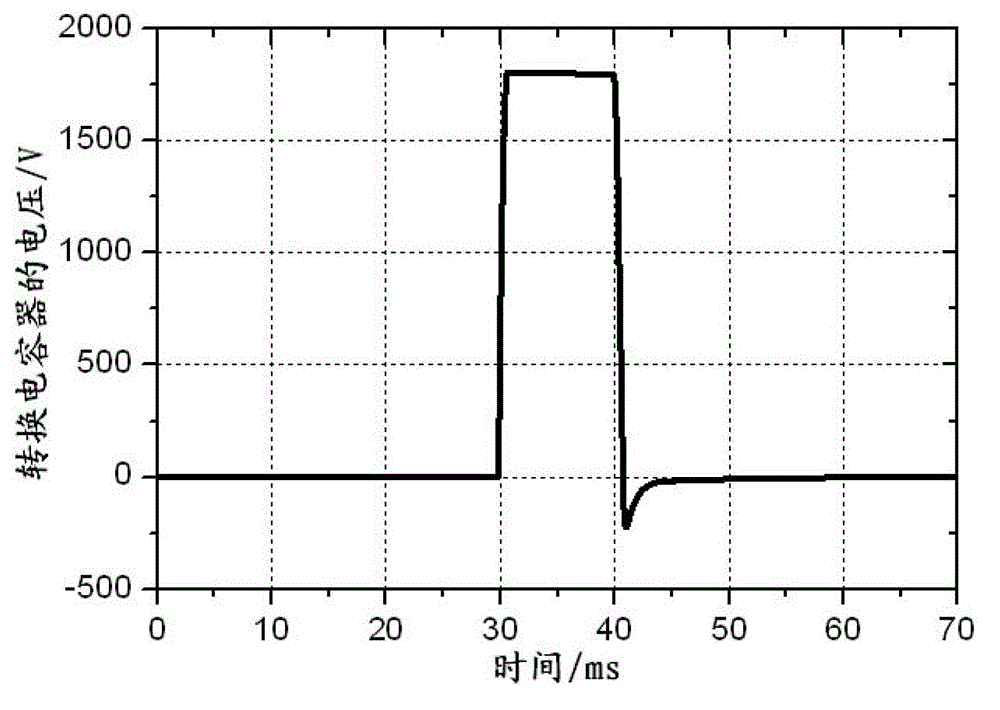
[0019] as attached figure 1 As shown, first close the power switch S 1 , the initial power supply device charges the primary and secondary coils of the superconducting and normal conducting hybrid pulse transformer in series, due to the diode D 3 The unidirectional conductivity, the load is not affected by the charging stage of the power supply; when the current of the series branch of the primary and secondary coils reaches a predetermined value, it remains constant; disconnect the power switch S 1 , part of the energy in the primary superconducting coil is transferred to the capacitor, and the other part is induced to the secondary constant conduction coil through mutual inductance, and then discharged from the secondary constant conduction coil to the load (ignoring the energy transfer of the secondary constant conduction coil itself to the load); When the current ...


PUM


Abstract

The invention discloses a pulsed power supply based on a superconductivity normal-conductivity combined pulse transformer, and the pulsed power supply is characterized in that a primary coil and a secondary coil of the superconductivity normal-conductivity combined pulse transformer adopt a different end serial-connection structure; when a power supply charging switch is closed, initial power supply charges a primary secondary coil in serial connection; and when the power supply charging switch is disconnected, partial energy in a primary superconductivity coil is transferred to a capacitor, and other energy is sensed to a secondary normal-conductivity coil through mutual inductance and then charges a load through the secondary normal-conductivity coil. After the transferring of the power is completed, the voltage of the capacitor reaches a maximal value, when a discharging switch is closed, and the load is discharged during the process that the capacitor charges the primary superconductivity coil in an opposite direction so as to complete the second pulse output. The pulsed power supply integrates the energy storage and discharging, large-current pulse can be outputted within a short time, and the pulsed power supply has advantages of small size, light weight and high energy conversion efficiency and has a promising application prospect and vast economic benefit.

Description

Technical field [0001] The invention belongs to a pulse current generating device in the technical field of pulse power, in particular to a pulse power supply based on a superconducting normal conduction hybrid pulse transformer. Background technique [0002] Pulse power technology was born in the 1930s. It is a technology for researching energy storage, compression, conversion and transmission. It first stores energy slowly, then performs form transformation, compression and adjustment, and finally in a very short time The energy is quickly released to the load to obtain various high-amplitude, high-power, and steep-front pulses. Pulse power technology is characterized by high voltage, high current, high power, and strong pulse, and has important scientific significance and application value in national defense research and industrial and civilian fields. In the military, high-power pulse power can be provided for nuclear fusion, high-current particle beam accelerators, el...

Claims


Application Information

Patent Timeline
IPC IPC(8): H02M9/04
Inventor 王豫吴锐严仲明桂志兴段晚晴
Owner SOUTHWEST JIAOTONG UNIV
Learn More