Method and device for cogeneration of synthesis ammonia gas and liquefied natural gas prepared through pressure gasification of crushed coal in fixed bed

A technology for liquefied natural gas and crushed coal pressurization, which is used in gas fuel, liquid contact hydrogen separation, petroleum industry, etc., and can solve problems affecting plant stability, safety, long-term reliable operation, low recovery rate, and high coupling degree.

Active Publication Date: 2012-10-31
SHANGHAI INT ENG CONSULTING
View PDF4 Cites 3 Cited by
  • Summary
  • Abstract
  • Description
  • Claims
  • Application Information

AI Technical Summary

Problems solved by technology

This process has the following disadvantages: 1. The process consumes a lot of energy and wastes resources; 2. The change of the CH4 fraction from the liquid nitrogen washing section affects the methane conversion section; 3. The process is long a

Method used


Image

  • Method and device for cogeneration of synthesis ammonia gas and liquefied natural gas prepared through pressure gasification of crushed coal in fixed bed
  • Method and device for cogeneration of synthesis ammonia gas and liquefied natural gas prepared through pressure gasification of crushed coal in fixed bed
  • Method and device for cogeneration of synthesis ammonia gas and liquefied natural gas prepared through pressure gasification of crushed coal in fixed bed

Examples


Embodiment 1

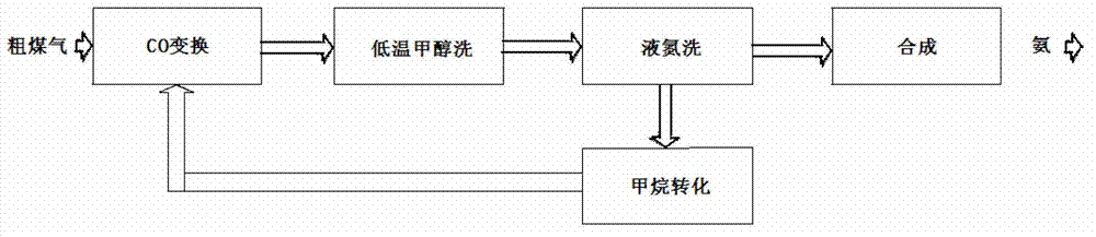
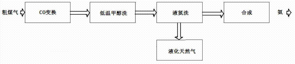
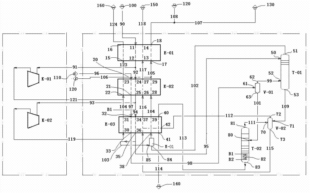
[0057] see image 3 , the fixed-bed pulverized coal pressurized coal gasification ammonia synthesis gas and liquefied natural gas cogeneration device shown in the figure includes high-pressure nitrogen cooler E-01, first raw gas cooler E-02, second raw gas cooler E-03, nitrogen scrubber T-01, methane rectification tower T-02, flash tank V-01, flash tank V-02, nitrogen expander K-01, nitrogen expander K-02.

[0058] The high-pressure nitrogen cooler E-01 has a high-pressure nitrogen inlet 11 , a high-pressure nitrogen outlet 12 , a fuel gas outlet 13 , a fuel gas inlet 14 , a nitrogen inlet 15 , a nitrogen outlet 16 , a synthesis gas inlet 17 and a synthesis gas outlet 18 .

[0059] The first raw gas cooler E-02 has raw gas inlet 20, raw gas outlet 21, nitrogen inlet 22, nitrogen outlet 23, high-pressure nitrogen inlet 24, high-pressure nitrogen outlet 25, fuel gas inlet 26, fuel gas outlet 27, synthesis gas Inlet 28, syngas outlet 29;

[0060] The second raw gas cooler E-03 ...

Embodiment 2

[0079] see Figure 4 , the fixed-bed pulverized coal pressurized coal gasification ammonia synthesis gas and liquefied natural gas co-production device of this embodiment is basically the same as that of Embodiment 1, except that 25 high-pressure nitrogen outlets separate high-pressure nitrogen delivery pipelines 93 and 94, and high-pressure nitrogen delivery pipeline 93 It is connected to the inlet of the nitrogen expander K-02, and the high-pressure nitrogen delivery pipeline 94 is connected to the high-pressure nitrogen inlet 34 of the second raw material gas cooler E-03. The raw material gas outlet 21 divides the raw material gas output pipeline 97 and the raw material gas output branch line A1, the raw material gas output branch line A1 is connected to the inlet of the reboiler 82 at the lower part of the methane distillation tower T-02, and the raw material gas output line 97 is connected to the first The raw material gas inlet 32 ​​on the raw material gas cooler E-03 is...


PUM


Abstract

The invention discloses a method for cogeneration of synthesis ammonia gas and liquefied natural gas prepared through pressure gasification of crushed coal in a fixed bed. In the method, through appropriate allocation of the processes among a high-pressure nitrogen gas cooler, raw material gas coolers, a nitrogen gas expander, a nitrogen washing column, flash tanks and methane rectifying columns, the cogeneration of the liquefied natural gas is achieved, so that the effects of low investment, low energy consumption, high heating value and high efficiency are achieved. The invention further discloses a device for cogeneration of synthesis ammonia gas and liquefied natural gas prepared through pressure gasification of crushed coal in the fixed bed.

Description

technical field [0001] The invention relates to the technical field of synthetic ammonia gas purification, in particular to a process for producing synthetic ammonia by utilizing the synthesis gas of BGL (British Gas-Lurgi) crushed coal slag pressurized gasifier and Lurgi crushed coal pressurized gasifier. The technical field of producing high-purity liquefied natural gas, especially relates to a method of using low-temperature liquid nitrogen as an absorbent to remove CO, Ar, and CH4 in the mixed gas, and during the process to refine the separated methane fraction into high-purity liquefied natural gas products The fixed-bed crushed coal pressurized coal gasification ammonia synthesis gas and high-purity liquefied natural gas co-production method and device, the method and device are suitable for synthesis gas (containing hydrogen, carbon monoxide, nitrogen, methane, argon) purification of low-energy synthetic ammonia field Consumption of new low-temperature liquid nitrogen w...

Claims


Application Information

Patent Timeline
IPC IPC(8): C01B3/52C10L3/10
Inventor 杨震东赵时红顾鹤燕陈晏支红利
Owner SHANGHAI INT ENG CONSULTING
Why Eureka
Try Eureka