
Process for producing gas-phase natural gas and liquid-phase natural gas through nitrogen-methane separation in nitrogen-containing natural gas

A technology of liquid-phase natural gas and gas-phase natural gas, which is applied in the direction of cold treatment separation, liquefaction, refrigeration and liquefaction, etc. It can solve the problems of high equipment investment, high energy consumption, and low condensation temperature of the overhead condenser of the rectification tower, so as to reduce equipment The effect of investment

Inactive Publication Date: 2012-11-07
CHONGQING ENDURANCE IND
View PDF8 Cites 24 Cited by
  • Summary
  • Abstract
  • Description
  • Claims
  • Application Information

AI Technical Summary

Problems solved by technology

Therefore, the separation process needs to be carried out under low temperature conditions, especially the temperature of the top condenser is low. Although the operating pressure of the rectification tower can be increased to make the rectification tower operate at a higher temperature, it is limited by the above reasons , the operating pressure of the rectification tower is lower than 2.7MPa
The condensation pressure at the top of the tower used in the aforementioned existing cryogenic rectification is basically the same as the operating pressure of the tower, so that the condensation temperature of the top condenser of the rectification tower is very low, high-grade cooling capacity is required, and the energy consumption is relatively high; The whole separation process has high energy consumption and high equipment investment

Method used


Image

  • Process for producing gas-phase natural gas and liquid-phase natural gas through nitrogen-methane separation in nitrogen-containing natural gas
  • Process for producing gas-phase natural gas and liquid-phase natural gas through nitrogen-methane separation in nitrogen-containing natural gas
  • Process for producing gas-phase natural gas and liquid-phase natural gas through nitrogen-methane separation in nitrogen-containing natural gas

Examples


example 1

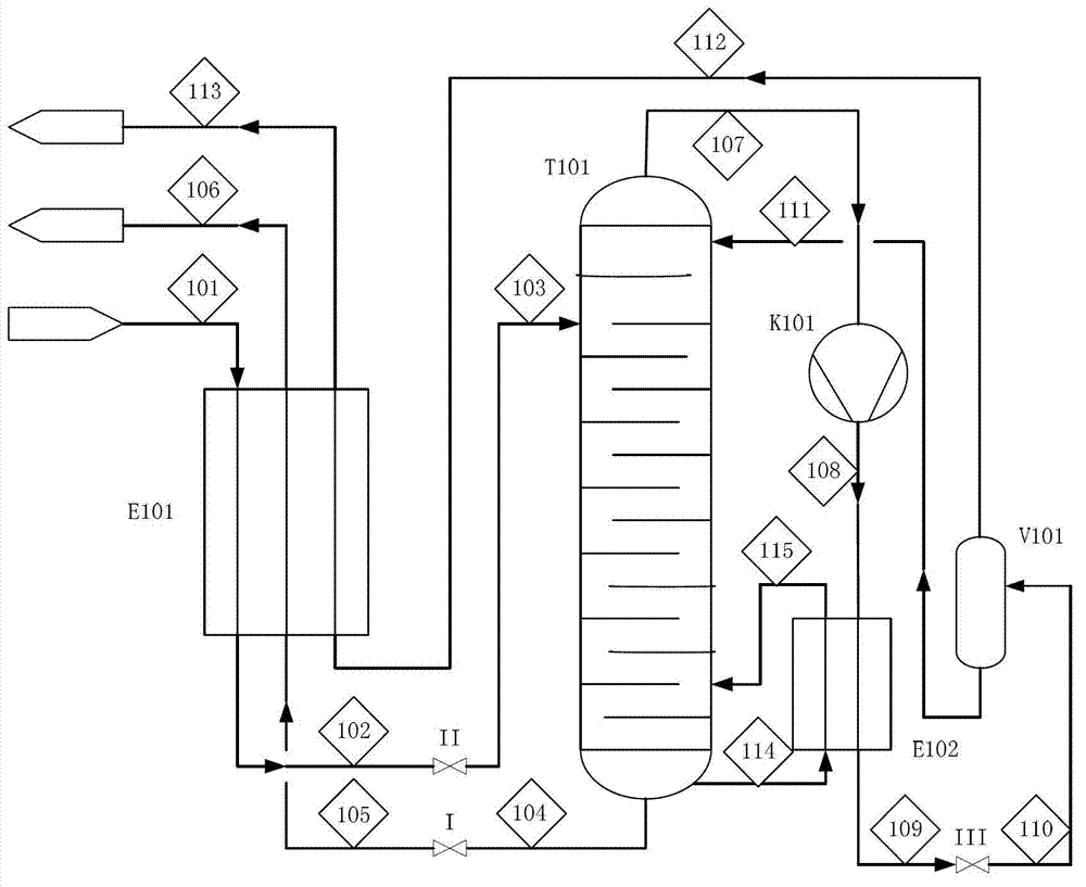
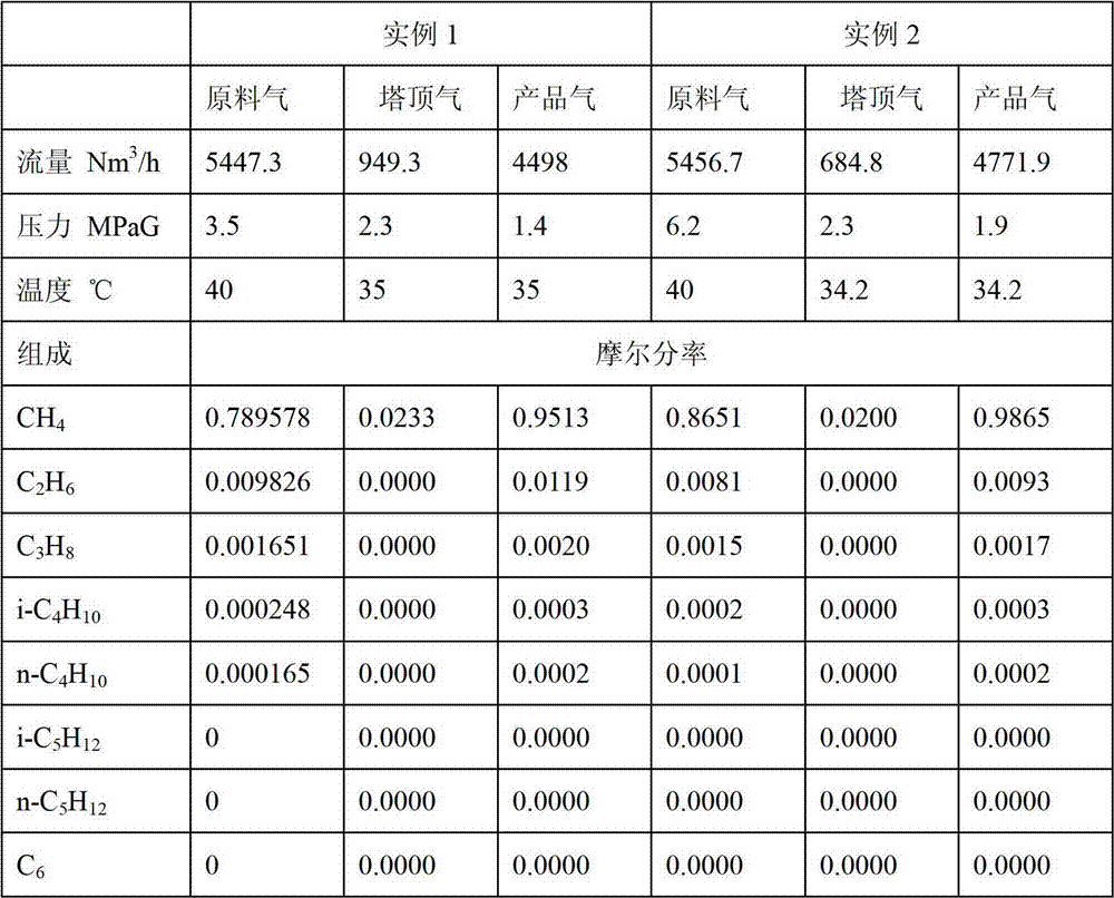
[0029] Such as figure 1 As shown, the nitrogen-methane separation of nitrogen-containing natural gas in offshore natural gas fields listed in this embodiment takes gaseous natural gas as the target product.

[0030] The purified raw gas 101 is first condensed into a liquid state 102 in the main heat exchanger E101, and then enters the rectification tower T101 from the middle inlet of the rectification tower T101 after passing through the throttle valve II to reduce the pressure.

[0031] The nitrogen-rich gas phase 107 flows out of the top of the rectification tower T101, and after being compressed by the first compressor K101, it flows into the top condenser and the bottom reboiler coupling heat exchanger E102 with the stream stream 108, and flows into the top of the tower from the bottom of the tower. The condenser and the bottom reboiler coupling heat exchanger E102 exchange heat in the liquid phase 114, and the nitrogen-enriched stream 109 flowing out of the top condenser ...

example 2

[0036] The flow chart of this embodiment is as follows figure 1 As shown, this embodiment cites the use of coke oven gas to synthesize natural gas containing nitrogen, and the separation of nitrogen and methane is realized through the present invention, and gaseous natural gas is the target product.

[0037] The pressure of the synthetic natural gas is 6.2MPa. The purified raw gas 101 enters the denitrification device, and is first condensed into a liquid 102 in the main heat exchanger E101, and then, after the pressure is reduced by the throttle valve II, it is discharged from the middle part of the rectification tower T101 The inlet enters the rectification column T101.

[0038] The nitrogen-rich gas phase 107 flows out of the top of the rectification tower T101, and after being compressed by the first compressor K101, it flows into the top condenser and the bottom reboiler coupled heat exchanger E102 with the stream stream 108, and flows into the top of the tower with the s...

example 3

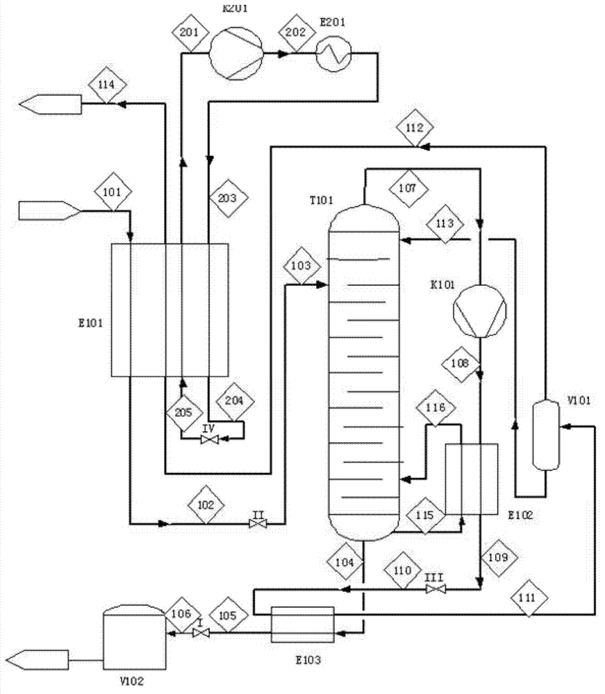
[0046] The schematic flow chart of this embodiment is attached figure 2 As shown, this embodiment cites the use of oil field gas as raw material gas after nitrogen flooding, and liquefied natural gas (LNG) as the target product after utilizing the nitrogen-methane separation process.

[0047] The oilfield gas pressure is 4.8MPa. The purified raw gas 101 enters the denitrification device, and is first condensed into a liquid 102 in the main heat exchanger E101, and then the pressure is reduced by the throttle valve II, and then enters from the middle of the rectification tower T101 Into the rectification column T101.

[0048] Among them, the main heat exchanger E101 also needs to adopt the way of mixed refrigerant circulation to obtain cooling capacity. In this example, CH 4 、C 2 h 4 、C 3 h 8 , i-C 5 h 12 The prepared mixed refrigerant 201 is compressed by the second compressor K201 to obtain a compressed mixed refrigerant 202, and the mixed refrigerant 202 is cooled by...


PUM


Abstract

The invention discloses a process for producing gas-phase natural gas and liquid-phase natural gas through nitrogen-methane separation in nitrogen-containing natural gas. A target product is natural gas or liquefied natural gas. According to the nitrogen-containing natural gas nitrogen-methane separation process, the gas on the top of the tower is compressed, the compressed tower top gas serves as a heat source of a bottom reboiler, a rectifying tower top condenser and the bottom reboiler are coupled to form a heat exchanger, a low-grade cold-flow condensing tower top product of the tower bottom is utilized, and the aims of saving the energy and reducing the consumption are fulfilled. The basic nitrogen-methane separation process comprises the following steps of: precooling raw material natural gas, rectifying tower separation, tower top gas-phase compression, reheating the tower top product and extracting and reheating the tower bottom product. The process has the characteristics of wide raw material natural gas application range, high methane recovery rate, low energy consumption and low equipment investment.

Description

technical field [0001] The present invention relates to a method for nitrogen-methane depth in conventional and unconventional nitrogen-containing natural gas, such as natural gas field gas, coal bed methane, oil field gas, synthetic ammonia relaxation gas, coke oven gas to natural gas, biogas, biomass or coal, etc. Process for obtaining gaseous natural gas and liquefied natural gas by cold separation. Background technique [0002] As a clean and efficient energy source, natural gas has attracted increasing attention. However, due to the different formation mechanisms of natural gas, natural gas fields contain CH 4 In addition to components, it also contains some light hydrocarbons such as C 2 h 6 , C 3 h 8 , i-C 4 h 10 , n-C 4 h 10 , i-C 5 h 12 , C 6 h 14 , some natural gas also contains benzene, toluene, and other aromatic hydrocarbons and CO 2 etc., the inert gas N in some gas fields 2 The content is even as high as more than 50%. With the development and u...

Claims


Application Information

Patent Timeline
IPC IPC(8): F25J3/02
CPCF25J3/0209F25J3/0233F25J3/0257F25J2200/02F25J2200/40F25J2200/76F25J2215/04F25J2230/08F25J2230/42F25J2270/12F25J2270/66F25J2290/34
Inventor 张金桥魏江涛蔡安宁
Owner CHONGQING ENDURANCE IND
Learn More