Reaction device utilizing sunlight for directly decomposing water to produce hydrogen
A technology of reaction device and water splitting, applied in hydrogen production, fuel cells, electrochemical generators, etc., can solve problems such as easy recombination, and achieve the effects of increasing reaction efficiency, low cost and simple structure
- Summary
- Abstract
- Description
- Claims
- Application Information
AI Technical Summary
Problems solved by technology
Method used
Image
Examples
Embodiment 1
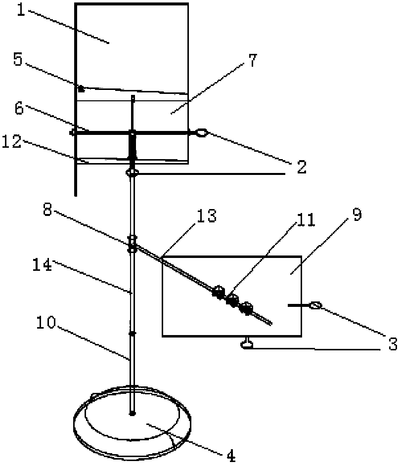
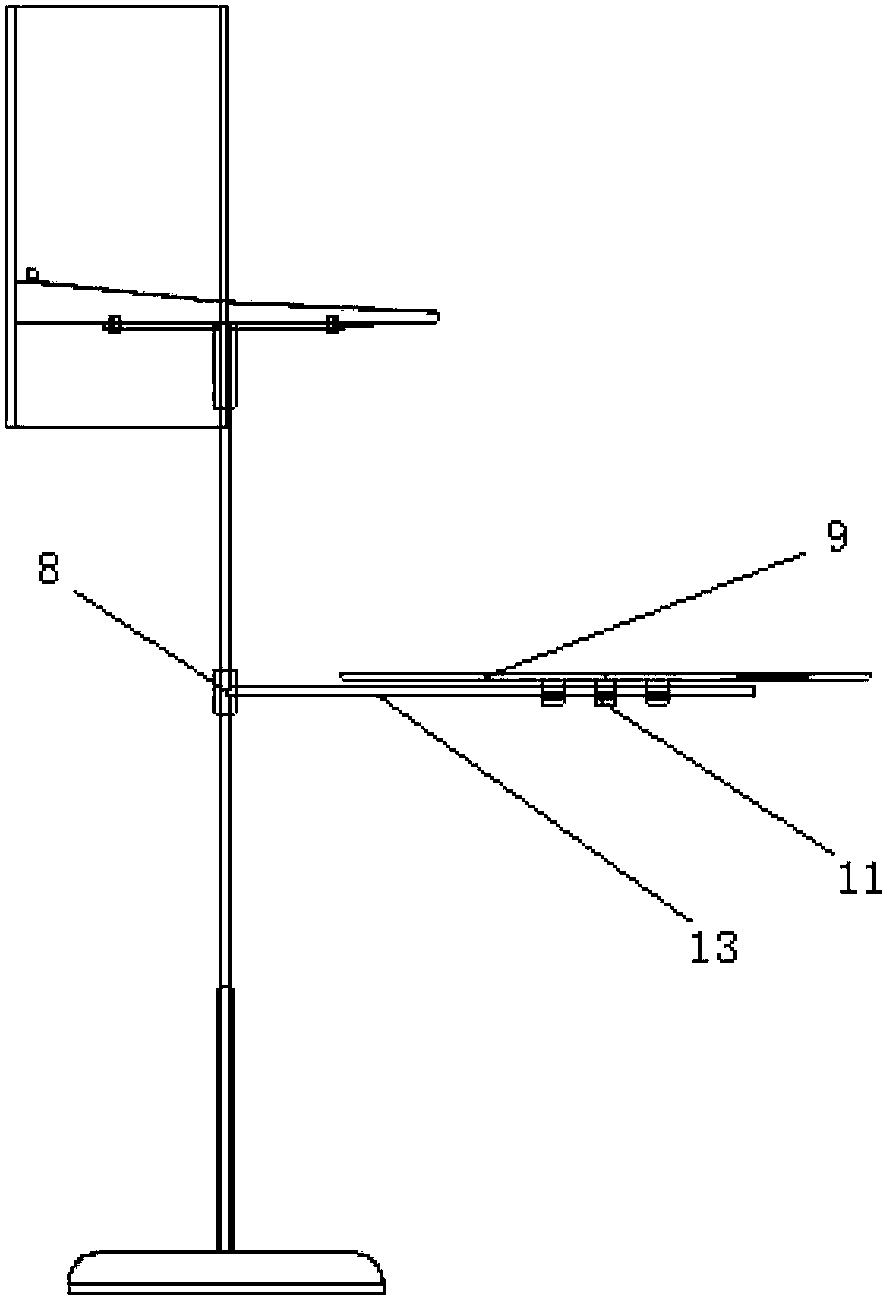
[0038] The present embodiment comprises: right-angle mirror 1, base 4, cross bracket 6, reactor 7, bottom surface mirror 9, reactor frame 12, wherein, reactor 7 is arranged on the cross bracket 6 by reactor frame 12, and the bottom surface reflects light The mirror 9 is fixed on the cross bracket 6, the right-angle mirror 1 is fixed on the reactor 7, the cross bracket 6 is fixed on the base 4, and the upper and lower surfaces of the reactor 7 are high light-transmitting glass.
[0039] A fluorescence calibration plate 2 is arranged on the reactor 7, and the fluorescence surface of the fluorescence calibration plate 2 faces downward.
[0040] The lower surface of the reactor 7 is horizontal, and the upper surface is inclined.
[0041] A gas outlet 5 is provided on one edge of the reactor 7, and a temperature sensor is provided on the gas outlet 5.
[0042] The mirror surface of the bottom reflector 9 is parallel to the lower bottom plate of the reactor 7 .
[0043] The edge o...
Embodiment 2
[0051] Embodiment 2 is a modification example of Embodiment 1.
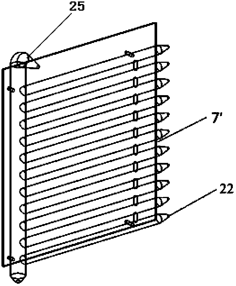
[0052] The difference between this embodiment and embodiment 1 is that the reactor 7 is preferably a tubular reactor 7'.
[0053] When using the tubular reactor 7', due to the need to avoid the impact of precipitation on the reaction, pulse gas needs to be added. This embodiment also includes a pulse generator 15 and a steam generator 16. The steam generator 16 generates steam by heating water with solar energy. The gas is generated by the steam generator 16, isobarically expanded in the pulse generator 15, and the gas is ejected when the piston rises to the outlet pipe. Pass into the gas inlet end 22 of tubular reactor 7 ', form disturbance, as Figure 5 shown.
[0054] Steam generator 16 is made up of concentrator and receiver, and the outer surface of receiver is painted black, and water is added inside, produces steam; As Figure 4 As shown, the steam enters the steam inlet 20 in the pulse generator from t...
Embodiment 3
[0057] Embodiment 3 is a variation of Embodiment 2.
[0058] The difference between this embodiment and embodiment 2 is that the tubular reactor 7' is a flat reactor.
[0059] The above three embodiments are specifically:
[0060] like figure 1 and figure 2 As shown, the base 4 is provided with a swivel pair 10, which can adjust the rotation of the whole device; on the swivel pair 10, a vertical shaft 14 is connected, and there are scales on the vertical shaft 14, which are used to adjust the height of the bottom reflector 9; the bracket crossbeam 13 passes through the first A one-dimensional moving pair 8 is connected with the vertical axis 14 . On the support crossbeam 13, connect the bottom reflector 9 by the second one-dimensional moving pair 11; the top of the vertical axis 14 fixes the reactor 7 by the cross bracket 6; The corresponding end of the second point 24 is the thickest. When using the tubular generator 7', the generator gas outlet 5 is located at the end o...
PUM
 Abstract
Description
Claims
Application Information
 - R&D
- Intellectual Property
- Life Sciences
- Materials
- Tech Scout
- Unparalleled Data Quality
- Higher Quality Content
- 60% Fewer Hallucinations
Browse by: Latest US Patents, China's latest patents, Technical Efficacy Thesaurus, Application Domain, Technology Topic, Popular Technical Reports.
© 2025 PatSnap. All rights reserved.Legal|Privacy policy|Modern Slavery Act Transparency Statement|Sitemap|About US| Contact US: help@patsnap.com


