Homogeneous flow-field circulating fluidized bed flue gas desulfurization technology

A circulating fluidized bed and flue gas technology, applied in chemical instruments and methods, dispersed particle separation, lighting and heating equipment, etc., can solve the problems of large reactor resistance drop, uneven flow field, low desulfurization efficiency, etc. Improve the reactivity, solve technical problems, and ensure the effect of desulfurization efficiency

Inactive Publication Date: 2012-11-21
北京博朗环境工程技术股份有限公司 +2
View PDF3 Cites 8 Cited by
  • Summary
  • Abstract
  • Description
  • Claims
  • Application Information

AI Technical Summary

Problems solved by technology

[0005] ① The rotary nozzle is expensive and the pulping system is complicated;
[0006] ② The flue gas flow rate in the absorption tower is very low, the tower diameter is large, and the floor area is large;
[0007] ③The Ca / S molar ratio is as high as 1.5, and higher quality lime is required, and the utilization rate of the absorbent is only ~50%;
[0008] ④ The slurry carries water and needs to be adjusted by adding water, which complicates the adjustment of the waterway caused by the temperature signal;
[0009] ⑤ The purified flue gas will corrode the rear dust removal equipment;
[0010] ⑥ During the operation of the device, the tower wall is easy to accumulate ash, and the bottom of the tower is easy to be blocked;
[0011] ⑦ Higher investment and higher operating costs (power consumption);
[0012] ⑧ Most of the by-products are CaSO 3 , is difficult to handle, and the use value is not high
The two move almost synchronously, with low chance of mutual friction and collision, and poor reaction effect;
[0015] ②The resistance drop of the reactor is relatively large, and the wear is serious (need to be made of wear-resistant steel);
[0017] ④The Ca / S molar ratio is as high as 1.5, the amount of water added to the absorbent (ie, humidifying ash) is limited (≤5%), the cycle rate is low (~25), the utilization rate is low, and the desulfurization efficiency is low;
[0018] ⑤ Only suitable for desulfurization and dust removal projects with medium and small flue gas volumes
[0020] ① The flow field is not uniform, even severe bias or partial eddy current, the desulfurization reaction on the same cross-section is very uneven, and it is difficult to achieve high-efficiency desulfurization;
[0021] ②The resistance drop of the reactor is relatively large (above 1500pa);
[0022] ③ Desulfurization ash sticks to the wall, agglomerates, collapses the bed, and tower blockage often occurs, making it difficult for the device to maintain long-term and stable operation
[0024] ① Lack of operating experience and low technical maturity;
[0025] ② The flue gas flow field deviation in the reactor is very serious, and a large part of the flue gas is short-circuited;
[0026] ③ The utilization rate of desulfurizer is low;
[0027] ④The volume of the reactor is very large;
[0028] ⑤ There is a large amount of ash accumulation in the lower part of the reactor. After being transported to the circulating ash humidifier, due to the high humidity of the material, pneumatic conveying cannot be used
The bucket elevator actually used needs to be equipped with a weighing system, which is close to classical, too heavy, and requires a lot of maintenance and repair work;
[0029] ⑥There are many rotating equipment and high power consumption

Method used


Image

  • Homogeneous flow-field circulating fluidized bed flue gas desulfurization technology
  • Homogeneous flow-field circulating fluidized bed flue gas desulfurization technology

Examples


Embodiment Construction

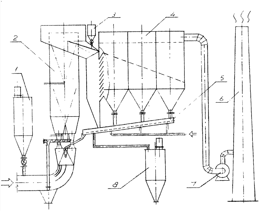
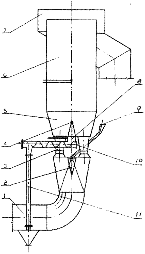
[0050] See figure 1 , Containing SO x , HCl, HF, NO x Boiler flue gas with pollutants such as dust enters the reactor 2 through the flue gas inlet flue. Used to remove SO x The slaked lime of acid gas such as HCl, HF, etc. is sent into the flue gas inlet flue by the star feeder at the bottom of the slaked lime bin. The inlet flue gas with a flow rate of ~16m / s sends the slaked lime and the circulating ash from the outlet of the absorbent distributor into the flue gas and absorbent accelerator. The flue gas, the slaked lime and the circulating ash are instantly accelerated and mixed uniformly. At this time, the humidification activation nozzle located at the bottom of the center of the reactor cylinder uniformly sprays water mist with extremely fine droplet size (40-60 μm), and the water mist rapidly mixes and evaporates with the flue gas surrounded by high-temperature flue gas ( Generally, it takes 1 to 3 seconds). While the ionic deacidification reaction is completed instantly...


PUM


Abstract

The invention relates to a homogeneous flow-field circulating fluidized bed flue gas desulfurization technology. A homogeneous flow-field circulating fluidized bed flue gas desulfurization reactor adopted by the homogeneous flow-field circulating fluidized bed flue gas desulfurization technology comprises a linear stream line-type flue gas inlet channel, a central built-in (center-explosion type) absorbent distributor, a flue gas accelerator, a humidifying activation nozzle, an annular flue gas outlet channel, an inner reflux circulating ash bin, a screw conveyer and an inner reflux circulating ash downcomer. The homogeneous flow-field circulating fluidized bed flue gas desulfurization technology has the advantages that a design is reasonable so that flue gas in the homogeneous flow-field circulating fluidized bed flue gas desulfurization reactor is acted upon by a homogeneous flow field, a homogeneous pressure field and a homogeneous temperature field; an absorbent has a high circulating ratio and a high utilization rate; a two-stage humidifying process can effectively improve reactivity of an absorbent; the humidifying activation nozzle is located in the center of a homogeneous flue gas flow field and a homogeneous absorbent flow field so that wall wetting, scaling and bed collapse are avoided effectively and flue gas desulfurization efficiency is improved effectively; the annular flue gas outlet channel is conducive to homogenization of a flow field in the homogeneous flow-field circulating fluidized bed flue gas desulfurization reactor and reduces a pressure drop and loads of a bag-type duster; and an inner reflux circulating conveying system can effectively prevent bed collapse and tower blocking so that safety, stability and a long running period of equipment are guaranteed.

Description

Technical field [0001] The invention relates to flue gas desulfurization technology and equipment, in particular to a semi-dry circulating fluidized bed flue gas desulfurization technology suitable for coal-fired power plants, garbage incineration power plants and sintering machines in the steel industry. Background technique [0002] There are about 300 kinds of flue gas desulfurization technologies in the world, but there are only more than ten kinds of industrially mature technologies, and the most widely used is the limestone-gypsum method. About 66% of my country's thermal power industry has installed flue gas desulfurization devices, and more than 90% of them use limestone-gypsum method. This method occupies a large area, high investment, complex process, serious equipment corrosion, large water consumption, and uses huge limestone resources, causing serious ecological damage. The utilization rate of the by-product (gypsum) is only 10%, and most of them are in a natural st...

Claims


Application Information

Patent Timeline
Patent Type & Authority Applications(China)
IPC IPC(8): B01D53/83B01D53/80B01D53/50F23J15/02
Inventor 刁经中徐纲赵钰慧黄灵芝蒋平菊
Owner 北京博朗环境工程技术股份有限公司
Why Eureka
Try Eureka