System and method for sensing VCSEL (Vertical Cavity Surface Emitting Laser) based ultrahigh-speed FBG (Fiber Bragg Grating)

A sensing system and fiber grating technology, applied in the field of ultra-high-speed sensing technology research, can solve problems such as the inability to achieve high-speed real-time demodulation, and achieve the effects of light weight, high sensitivity, and fast demodulation speed

Inactive Publication Date: 2012-11-28
JINAN UNIVERSITY
View PDF1 Cites 23 Cited by
  • Summary
  • Abstract
  • Description
  • Claims
  • Application Information

AI Technical Summary

Problems solved by technology

For example, in 2010, Honglei Guo, Gaozhi Xiao and others reported a wavelength scanning fiber grating demodulation method based on chip piezoelectric control AWG, "Wavelength Interrogator Based on Closed-Loop Piezo-Electrically Scanned Space-to-Wavelength Mapping of an Arrayed Waveguide Grating”IEEE J.Lightwave Technol.,vol.28,p.2654,2010. This method has the characteristics of wide wavelength scanning range and easy system integration, but it is essentially a segmented wavelength interval scanning demodulation, through The energy ratio algorithm between the two channels calculates the reflection wavelength of the grating, which cannot achieve high-speed real-time demodulation

Method used


Image

  • System and method for sensing VCSEL (Vertical Cavity Surface Emitting Laser) based ultrahigh-speed FBG (Fiber Bragg Grating)
  • System and method for sensing VCSEL (Vertical Cavity Surface Emitting Laser) based ultrahigh-speed FBG (Fiber Bragg Grating)
  • System and method for sensing VCSEL (Vertical Cavity Surface Emitting Laser) based ultrahigh-speed FBG (Fiber Bragg Grating)

Examples


Embodiment 1

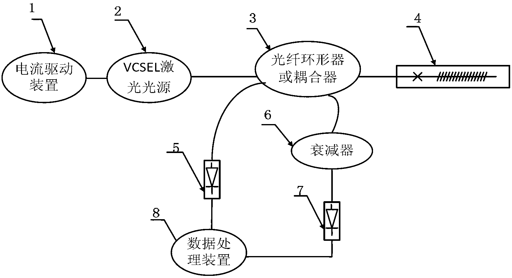
[0032] Such as figure 1 As shown, a VCSEL-based ultra-high-speed fiber grating sensing system in this embodiment includes a VCSEL laser light source 2, a sensing probe 4 and a photoelectric conversion module, and the VCSEL laser light source 2, sensing probe 4 and photoelectric conversion module three Or connect through fiber optic coupler 3. It can also be replaced by a fiber optic circulator in practical applications. The VCSEL laser light source 2 is driven by a current driving device 1 . The photoelectric conversion module is divided into two parts, the first part includes a first photodetector 5, which is used to convert the reflected light signal containing environmental vibration information into a vibration electrical signal, and the second part includes a second photodetector 7 and an attenuator 6. The attenuator 6 is used to attenuate the optical signal of the periodically modulated laser output by the VCSEL laser light source 2 through the fiber coupler 3 by a cer...


PUM

PropertyMeasurementUnit
sizeaaaaaaaaaa

Abstract

The invention discloses a system for sensing a VCSEL (Vertical Cavity Surface Emitting Laser) based ultrahigh-speed FBG (Fiber Bragg Grating). The system comprises a VCSEL laser light source, a sensing probe and a photovoltaic conversion module, wherein the sensing probe comprises an inclined FBG and a cladding-fiber core energy re-coupling structure; the photovoltaic conversion module comprises a vibration information demodulating part and an attenuation reference obtaining part; an external data processing device gives a normalized output of the system. The realization method comprises the steps of: outputting high-speed periodically modulated laser to an optical fiber coupler by the LCSEL laser light source, wherein one path of optical signals are subjected to attenuation of an attenuator and photovoltaic conversion to obtain reference electric signals, and the other path of optical signals enters into an optical fiber probe to obtain reflected light signals including environment vibration information and then is subjected to the photovoltaic conversion to obtain vibration electric signals; and dividing the reference electric signals by the vibration electric signals to obtain the normalized output of the sensing system. The system and method for sensing VCSEL based ultrahigh-speed FBG, disclosed by the invention, have the advantages of ultrahigh-speed (higher than MHz) and high-sensitivity (superior to 15 dB) vibration sensing, high system integration level, low cost (no need of filtering), normalized output for removing temperature change influence and high stability.

Description

technical field [0001] The invention relates to the research field of ultra-high-speed sensing technology, in particular to an ultra-high-speed fiber grating sensing system based on VCSEL (Vertical Cavity Surface Emitting Laser, Vertical Cavity Surface Emitting Laser). Background technique [0002] Ultra-high-speed sensing technology has extremely important application requirements in the fields of seismic wave detection (geological exploration, petroleum industry, etc.), transient deformation and shock wave analysis (locomotive traffic safety, military weapon testing, etc.). Optical fiber sensing technology, with its small size, high sensitivity, anti-electromagnetic interference, light weight, and suitable for remote monitoring, has been more and more widely used in the field of ultra-high-speed sensing. [0003] Due to the natural compatibility between fiber gratings and optical fibers, it is easy to connect multiple fiber gratings in series on one fiber to form a fiber g...

Claims


Application Information

Patent Timeline
Patent Type & Authority Applications(China)
IPC IPC(8): G01H9/00G01K11/32G02B6/036G01K11/3206
Inventor 郭团关柏鸥杜发尚立斌刘甫
Owner JINAN UNIVERSITY
Why Eureka
Try Eureka