Beam coupling and focusing device for laser diode array

A laser diode and focusing device technology, applied in optics, optical components, instruments, etc., can solve problems such as multiple insertion losses, reduce system compactness, etc., and achieve the effects of small insertion loss, compact structure, and improved coupling efficiency

Active Publication Date: 2012-12-05
杭州盛镭激光科技有限公司
View PDF9 Cites 13 Cited by
  • Summary
  • Abstract
  • Description
  • Claims
  • Application Information

AI Technical Summary

Problems solved by technology

[0008] Although the third and fourth solutions have high coupling efficiency, they both insert diffractive opt

Method used


Image

  • Beam coupling and focusing device for laser diode array
  • Beam coupling and focusing device for laser diode array
  • Beam coupling and focusing device for laser diode array

Examples


Embodiment 1

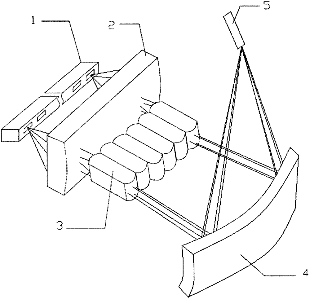
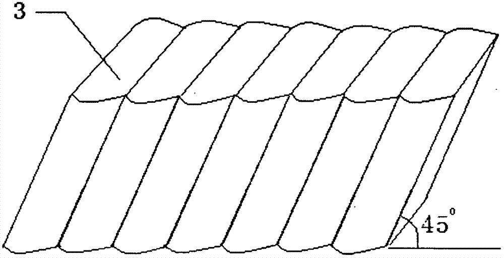
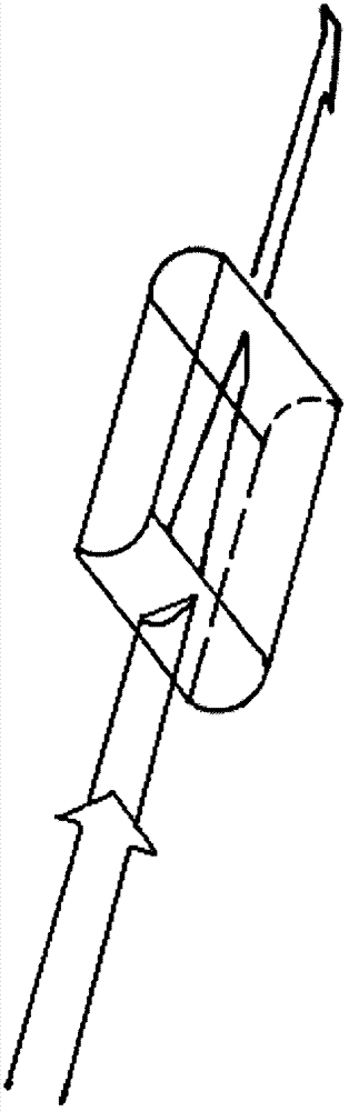
[0034] The laser diode array 1 in this embodiment is composed of 8 laser diode emitting units, and the emitting area of ​​a single laser diode emitting unit is 1×100 μm 2 , the full-angle divergence angle of the fast axis is 35°, and the full-angle divergence angle of the slow axis is 8°. The fast-axis collimation unit 2 is a microcylindrical lens with a height of 500 μm, a thickness of 2 mm, a length of 10 mm, an optical focal length of 1 mm, and a distance of 200 μm from the laser diode array. The laser has a dielectric film with high transmittance. After the fast-axis beam emitted by the laser diode array 1 is compressed by the fast-axis collimation unit 2 to compress the fast-axis divergence angle, the fast-axis beam is shaped into a parallel beam with a height of 200 μm. The distance between the beam rotation array 3 and the fast-axis collimation unit 2 is 600 μm. The beam rotation array 3 is composed of 8 cylindrical microlens groups inclined at 45°. The main axis of a ...


PUM

PropertyMeasurementUnit
Angleaaaaaaaaaa

Abstract

The invention discloses a beam coupling and focusing device for a laser diode array. The beam coupling and focusing device comprises the laser diode array, a fast axis collimation unit and a beam rotary array, which are sequentially placed along the forward direction of beams, wherein a toric reflecting mirror and an optical axis are placed at a certain included angle; and a target optical unit is positioned at a focal point of the toric reflecting mirror. The beam coupling and focusing device can couple and focus the beams which are emitted by the laser diode array. The beam coupling and focusing device has the advantages of simple structure, convenience for installation, low insertion loss, high coupling efficiency and high structure compactness.

Description

technical field [0001] The invention relates to beam shaping and coupling of a laser diode array, in particular to a beam coupling focusing device for optical fiber coupling or solid laser pump coupling of a laser diode array. Background technique [0002] Over the years, laser technology has developed rapidly, and its application scope has also expanded day by day. Laser technology is constantly improving our quality of life. There are two types of pump light sources for solid-state lasers: xenon or krypton lamps and laser diodes. Laser diodes have the characteristics of small size, light weight, high photoelectric conversion efficiency, long life and direct modulation, and have a bright market future. As the cost of laser diodes decreases, in some fields, laser diodes are gradually replacing traditional pump xenon lamps. In some industrial applications, diode lasers are used as laser light sources to be directly applied to cutting, welding and surface treatment, etc. ...

Claims


Application Information

Patent Timeline
IPC IPC(8): G02B27/09
Inventor 余勤跃扈金富
Owner 杭州盛镭激光科技有限公司
Why Eureka
Try Eureka