Preparation method for pyroelectric thick film detector with silicon cup groove structure

A technology for structural heat and detectors, applied in electrical radiation detectors, thermoelectric devices with thermal changes in dielectric constant, etc. Infrared performance, easy operation, and the effect of protecting integrity

Inactive Publication Date: 2012-12-12
UNIV OF ELECTRONICS SCI & TECH OF CHINA
View PDF2 Cites 4 Cited by
  • Summary
  • Abstract
  • Description
  • Claims
  • Application Information

AI Technical Summary

Problems solved by technology

First of all, thick film materials have high sintering temperature and poor material properties.
Because materials with excellent performance can be prepared by adjusting the components, many phases are added when preparing thick film materials, and uneven mixing and poor density of materials will lead to high sintering temperatures and poor performance of the obtained materials
Second and most serious flaw: thick film materials are prone to cracking
In order to obtain a thick film with a high surface smoothness, the thick film material must be subjected to isostatic pressing, and the thick film will bear a certain pressure during isostatic pressing, because the bottom of the thick film is supported by a barrier material to balance the downward pressure. pressure, but there is no support on the side of the thick film, the force of the thick film with uneven surface will be unbalanced, and the side will bear the outward tension. In addition, if the prepared thick film material is mixed unevenly, there will be uneven Uniform porosity and gaps, cracking occurs easily after thick film is subjected to pressure
Cracking seriously damages the quality of the thick film, and is also not conducive to the preparation of the upper electrode, greatly reducing the yield of infrared detectors

Method used


Image

  • Preparation method for pyroelectric thick film detector with silicon cup groove structure
  • Preparation method for pyroelectric thick film detector with silicon cup groove structure
  • Preparation method for pyroelectric thick film detector with silicon cup groove structure

Examples


Embodiment Construction

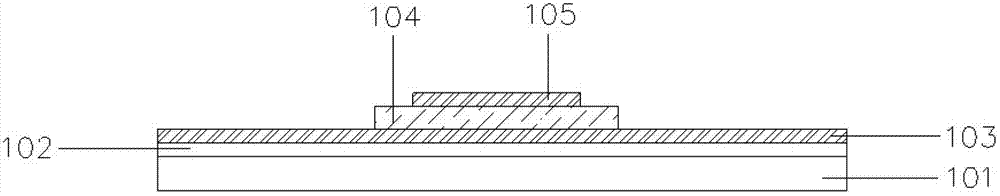
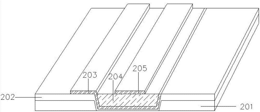
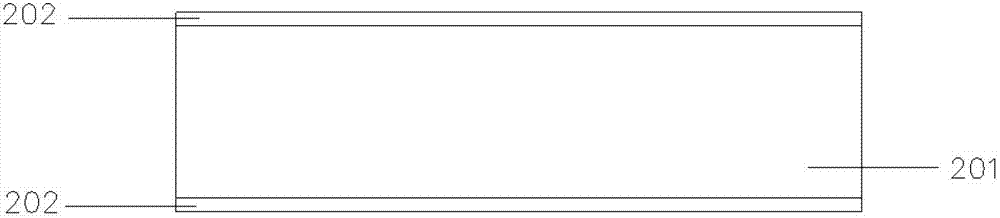
[0038]In order to solve the problems of poor performance of thick film materials in pyroelectric thick film detectors, high sintering temperature and easy cracking of thick film materials, the purpose of the present invention is to provide a new pyroelectric thick film detector and its preparation method. The present invention is based on the micro-mechanical process, and adopts a through-silicon via interconnection manufacturing technology to prepare a groove structure with a certain slope and depth in the substrate. After preparing the barrier layer and the bottom electrode in the groove, deposit the pyroelectric thick film material, so that it just fills the entire groove, the surface of the thick film material is exactly the same height as the substrate surface, then the thick film is isostatically pressed, sintered into porcelain at high temperature, and finally the upper layer is drawn out by photolithography and sputtering. electrode. In order to ensure the smooth extra...


PUM


Abstract

The invention discloses a pyroelectric thick film detector with a silicon cup groove structure, and belongs to the technical field of electronic materials and components. The pyroelectric thick film detector with the silicon cup groove structure comprises a silicon substrate, a bottom electrode and an upper electrode, wherein the upper surface of the silicon substrate is provided with a groove; a pyroelectric thick film material is filled in the groove; the bottom electrode is led out through the side wall of the groove; and the included angle between the upper surface of the silicon substrate and the side wall of the groove provided with the bottom electrode is an obtuse angle. The pyroelectric thick film detector with the silicon cup groove structure is favorable for improving the quality of a thick film and the yield of detectors, so that high performance is realized by the pyroelectric thick film detector.

Description

technical field [0001] The invention relates to a manufacturing process of a pyroelectric infrared detector, in particular to a method for preparing a pyroelectric thick-film detector with a silicon cup groove structure, and belongs to the technical field of electronic materials and components. Background technique [0002] Pyroelectric infrared detectors work by using the pyroelectric effect of pyroelectric materials. When the pyroelectric material is in a constant temperature environment lower than the Curie temperature, its self-polarized charge density remains unchanged, and these charges are neutralized by charged ions in the air; when infrared radiation enters the pyroelectric material and is absorbed by the material, As the temperature of the material increases, the self-polarization intensity decreases, that is, the surface charge density decreases. In this way, excess neutralization charges exist on the surface of the pyroelectric material, and these charges are ou...

Claims


Application Information

Patent Timeline
Patent Type & Authority Applications(China)
IPC IPC(8): H01L37/02G01J5/10
Inventor 吴传贵陈冲彭强祥曹家强罗文博帅垚张万里王小川
Owner UNIV OF ELECTRONICS SCI & TECH OF CHINA
Why Eureka
Try Eureka