
Transient temperature measuring system for diesel engine piston and measuring method thereof

A measurement system and transient temperature technology, applied in the direction of measuring heat, thermometers, measuring devices, etc., can solve the problem of low precision of hardness plug method and fusible alloy method, long response time of ordinary thermocouple measurement method, and inability to perform transient continuous Measurement and other problems, to achieve the effect of short response time, solve the problem of thin film thermocouple lead wire connection, and solve the problem of temperature test

Active Publication Date: 2013-01-02
DALIAN JIAOTONG UNIVERSITY
View PDF2 Cites 22 Cited by
  • Summary
  • Abstract
  • Description
  • Claims
  • Application Information

AI Technical Summary

Problems solved by technology

However, these methods have their own limitations. The response time of the ordinary thermocouple measurement method is long, which cannot meet the requirements; the hardness plug method and the fusible alloy method have low precision, long response time, and cannot be used for transient continuous measurement.

Method used


Image

  • Transient temperature measuring system for diesel engine piston and measuring method thereof
  • Transient temperature measuring system for diesel engine piston and measuring method thereof
  • Transient temperature measuring system for diesel engine piston and measuring method thereof

Examples


Embodiment Construction

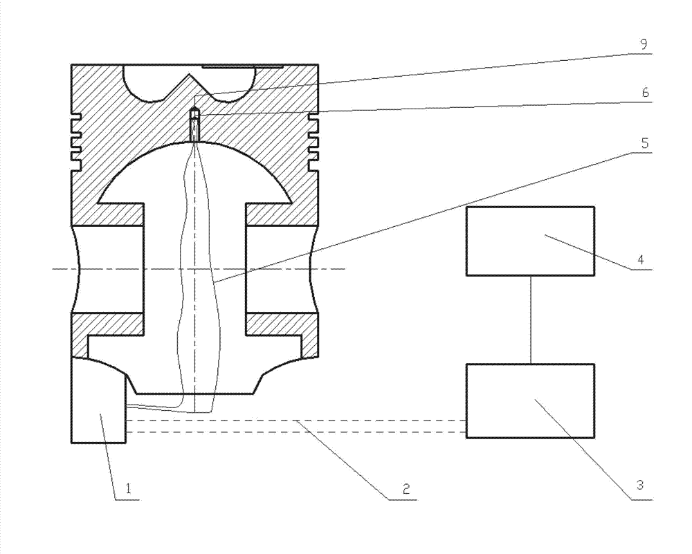
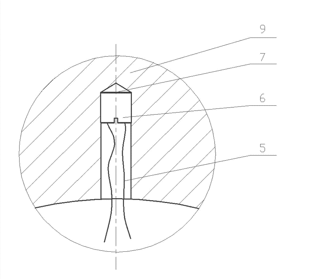
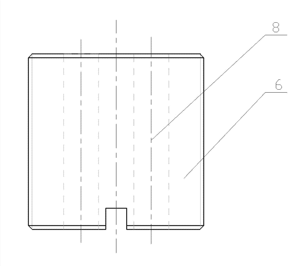
[0032] The present invention will be further described below in conjunction with the accompanying drawings. Such as Figure 1-9 As shown, the present invention mainly includes a thin film thermocouple 7 , a temperature measuring screw 6 and a compensation wire 5 . Place the temperature measuring screw 6 on the point to be measured on the piston 9, use the thin film thermocouple 7 on the temperature measuring screw 6 to collect the temperature signal of the diesel engine piston 9, and transmit it to the data acquisition, amplification and transmitting device 1 connected to the piston 9 through the compensation wire 5 . The specific implementation process is as follows:

[0033] 1. Make a mask: select two rectangular plates with the same length and width and different thicknesses; first process the thin rectangular plate 10 with a plurality of through holes in the shape of “Z” on an ultra-precision wire cutting machine, that is, the thin rectangular plate 10 Process it into a...


PUM

PropertyMeasurementUnit
Thicknessaaaaaaaaaa
Thicknessaaaaaaaaaa
Seebeck coefficientaaaaaaaaaa

Abstract

The invention discloses a transient temperature measuring system for a diesel engine piston and a measuring method thereof. The system comprises a data acquiring, amplifying and transmitting device, a signal receiving device, a computer, a temperature measuring screw and a compensating lead, wherein the temperature measuring screw is connected with the data acquiring, amplifying and transmitting device through the compensating lead; the data acquiring, amplifying and transmitting device is connected with the signal receiving device through a wireless transmission signal; and the upper end face of the temperature measuring screw is provided with a film thermocouple. The method comprises the following steps of: making a mask and a mask clamp; making a temperature measuring screw; installing; and measuring. According to the measuring system, temperature is measured by using an advanced film thermocouple preparation technology, so that short dynamic response time is ensured, high temperature measuring accuracy is realized, and continuous measurement can be performed. Meanwhile, a small screw structure is adopted, and a sensor is easy to manufacture and can be placed on the piston easily; and the transient temperature measuring system is simple in structure, is convenient to replace, and can be produced in a standard way. Due to the adoption of the transient temperature measuring system and the measuring method thereof, the problems of temperature testing of the diesel engine piston in a severe working environment and the problem of lead connection of the film thermocouple are solved.

Description

technical field [0001] The invention relates to a testing method for transient temperature, in particular to a diesel engine piston transient temperature measuring system and a measuring method thereof. Background technique [0002] As the power of vehicles and ships, the thermal efficiency and reliability of internal combustion engines are the symbols representing the level of internal combustion engines in a country. And high thermal efficiency is often at the expense of high heat load, so the heat load problem has attracted much attention with the strengthening of the engine. The heat load problem is mainly reflected in the frequent thermal damage failures of some important parts that constitute the combustion chamber. On the piston, it is mainly manifested in: head ablation, block loss, thermal cracking, overheating of the head ring area, piston ring stuck, Cylinder pulling, broken ring, etc. The successive problems have seriously threatened the thermal reliability of ...

Claims


Application Information

Patent Timeline
IPC IPC(8): G01K7/02
Inventor 崔云先盛晓幸殷俊伟邢磊
Owner DALIAN JIAOTONG UNIVERSITY
Learn More