Automatic control system of unmanned aerial vehicle (UAV)

An automatic control system and unmanned aerial vehicle technology, applied in the direction of attitude control, etc., can solve the problems of affecting image clarity, mixing noise, increasing the difficulty of aerial photography, etc.

Active Publication Date: 2013-01-02
JIANGSU ROBOBOR ROBOT TECH CO LTD
View PDF3 Cites 27 Cited by
  • Summary
  • Abstract
  • Description
  • Claims
  • Application Information

AI Technical Summary

Problems solved by technology

[0006] (1) In the daily helicopter inspection work, the working methods of helicopter inspection mainly include: visual inspection, instrument observation and instrument automatic inspection. Recorded images are used to judge line faults and hidden dangers. Obviously, this method is inefficient, greatly affected by subjective and objective factors, and measurement accuracy is difficult to guarantee, and because it is supplemented by manual inspection, the degree of automation of detection is greatly reduced;
[0007] (2) In order to protect the personal safety of the aerial photography personnel, the distance between the helicopter and the wires is generally 20-30 meters away. Such a long distance undoubtedly increases the difficulty of aerial photography between the camera and the measurement object, and sometimes affects to image clarity;
[0008] (3) For the images taken by helicopters, they are generally stored in a memory after aerial photography by the camera, and then through the video research after the event, the questionable areas are analyzed. In order to ensure the accuracy, sometimes a second or even Multiple shootings will undoubtedly increase the cost of the test;
[0009] (4) During the helicopter inspection process, visible light digital cameras, digital cameras, infrared thermal imagers and

Method used


Image

  • Automatic control system of unmanned aerial vehicle (UAV)
  • Automatic control system of unmanned aerial vehicle (UAV)
  • Automatic control system of unmanned aerial vehicle (UAV)

Examples


Embodiment Construction

[0029] The preferred embodiments of the present invention will be described in detail below in conjunction with the accompanying drawings, so that the advantages and features of the present invention can be more easily understood by those skilled in the art, so as to define the protection scope of the present invention more clearly.

[0030] With the continuous development and maturity of microelectronics technology and computer integrated chip manufacturing technology, DSP processors are not only widely used in communication and video signal processing due to their fast computing capabilities, but also gradually used in various advanced control systems. AD's ADSP-21xx series provides low-cost, low-power consumption, high-performance processing capabilities and solutions. The ADSP-2188 instruction execution speed is as high as 75MIPS, plus an independent arithmetic logic unit, with powerful digital signal processing ability. In addition, large-capacity RAM is integrated into t...


PUM


Abstract

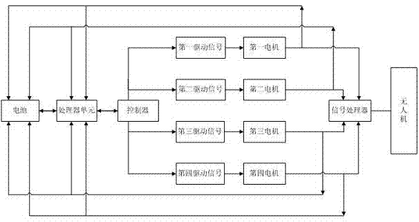
The invention discloses an automatic control system of an unmanned aerial vehicle (UAV). The automatic control system comprises a processor unit, a controller, a first motor, a second motor, a third motor, a fourth motor, a signal processor and an unmanned aerial vehicle, wherein the processor unit transmits control signals to the controller; the controller divides the control signals into a first driving signal, a second driving signal, a third driving signal and a fourth driving signal; and the first driving signal, the second driving signal, the third driving signal and the fourth driving signal are used for controlling the first motor, the second motor, the third motor and the fourth motor respectively, and the first driving signal, the second driving signal, the third driving signal and the fourth driving signal which pass through the first motor, the second motor, the third motor and the fourth motor are compounded by the signal processor to control the movement of the unmanned aerial vehicle. The automatic control system of the UAV breaks through the limitation of high-voltage line patrol of 'giving priority to helicopter patrol and giving supplement to manual patrol' in the prior art.

Description

technical field [0001] The present invention relates to the technical field of UAV (Unmanned Aerial Vehicle), and in particular to an automatic control system of UAV. Background technique [0002] With the rapid development of information technology, the application of GPS (Global Positioning System) and high-resolution aerial photography sensors in aerial photography has greatly developed aerial photogrammetry technology, and has become a remote sensing, remote control , Telemetry technology and computer technology as one of the new practical technology. After entering the 21st century, this technology has been gradually applied from the military field to the civilian and industrial fields. The recently proposed concepts of "digital city" and "digital earth" are the concrete manifestation of this technology being transferred to civilian use. [0003] Aerial photogrammetry technology is to digitize and two-dimensionally process aerial images collected during flight to obtai...

Claims


Application Information

Patent Timeline
IPC IPC(8): G05D1/08
Inventor 张好明王应海史小波
Owner JIANGSU ROBOBOR ROBOT TECH CO LTD
Why Eureka
Try Eureka