
Deadline-fixed PFM (pulse frequency modulation) mode switching power supply controller

A technology of cut-off time and switching power supply, which is applied in the application fields of switching power supply controllers and portable mobile devices. It can solve problems such as complex circuit structure, unstable sub-harmonics, and complex control methods, and achieve simple circuit structure and output ripple. Small, high-efficiency effects

Inactive Publication Date: 2013-01-09
UNIV OF ELECTRONIC SCI & TECH OF CHINA
View PDF7 Cites 21 Cited by
  • Summary
  • Abstract
  • Description
  • Claims
  • Application Information

AI Technical Summary

Problems solved by technology

PWM modulation is currently the most commonly used modulation method due to its simple control method. However, when operating in continuous current mode (CCM) and changing in a wide range of duty cycles, it will lead to sub-harmonic instability problems, which require a slope compensation, the circuit structure will become complex
The constant width variable frequency PFM has a fixed conduction time in one cycle, and its efficiency is high at light load, but at this time the ripple voltage is the largest, and it cannot work in the continuous current mode, because the current flowing through the inductor fluctuates greatly in the discontinuous mode , which puts forward higher requirements for the volume of the inductor
The hybrid modulation mode of PWM and PFM is rarely used due to the complex control method
In addition, the above modulation methods work under heavy load conditions, and the power switching devices work at the highest switching frequency, resulting in large switching losses and low efficiency.

Method used


Image

  • Deadline-fixed PFM (pulse frequency modulation) mode switching power supply controller
  • Deadline-fixed PFM (pulse frequency modulation) mode switching power supply controller
  • Deadline-fixed PFM (pulse frequency modulation) mode switching power supply controller

Examples


Embodiment Construction

[0028] In order to make the objectives and technical solutions of the present invention clearer, the present invention will be further described in detail below in conjunction with specific embodiments and with reference to the accompanying drawings.

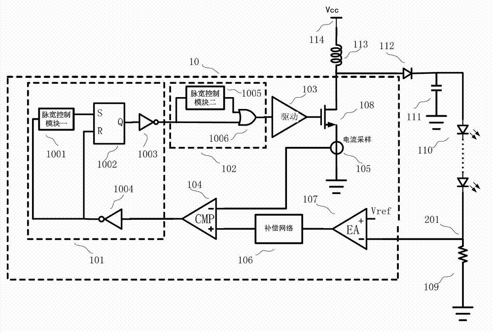
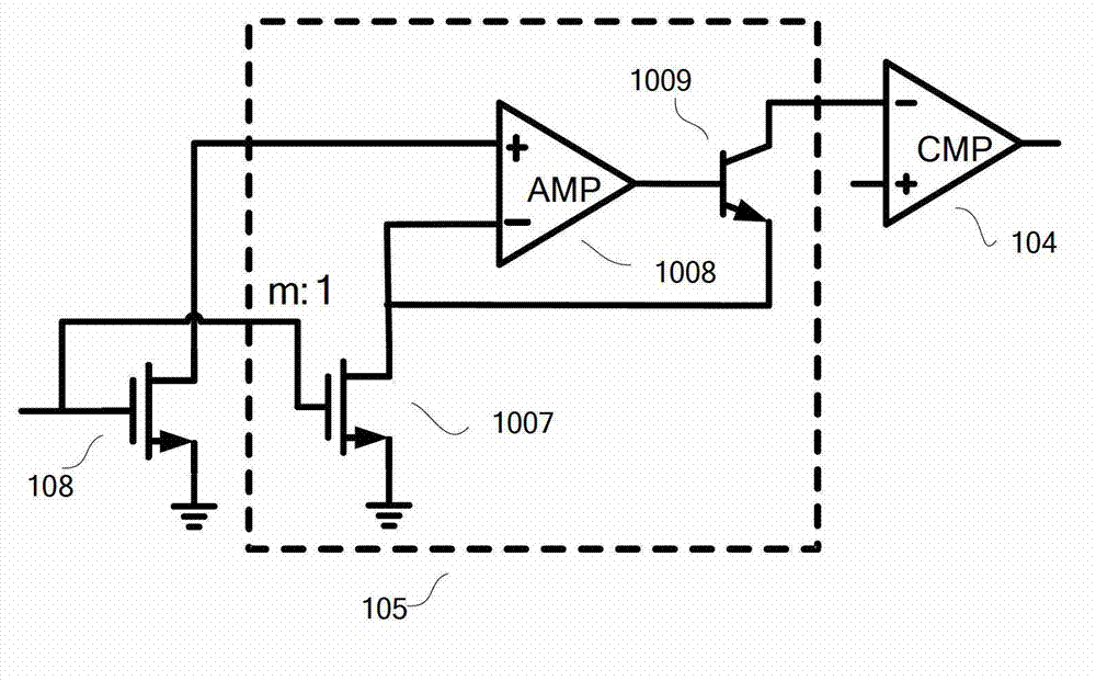
[0029] figure 1 It is a fixed cut-off time PFM modulation control architecture of the present invention and an application circuit diagram in LED constant current driving. The PFM mode switching power supply controller 10 with a fixed cut-off time includes an error amplifier 107, a frequency compensation network 106, a comparator 104, a fixed cut-off time PFM control module 101, a maximum frequency limit module 102, a power switch tube drive circuit 103, and current sampling Module 105 and power switch tube 108. The specific circuit connection relationship is as described above.

[0030] When the switching power supply controller is specifically applied to LED constant current driving, one end of the inductor 113 is connected to the...


PUM


Abstract

The invention relates to a deadline-fixed PFM (pulse frequency modulation) mode switching power supply controller belonging to the technical field of power integrated circuits, and mainly relates to the application area of BOOST switching power supplies. The switching power supply controller comprises an error amplifier (107), a frequency compensation network (106), a comparator (104), a deadline-fixed PFM control module (101), a maximum frequency limit module (102), a power switching tube drive circuit (103), a current sampling module (105) and a power switch (108). The PFM controller architecture is simple in implementation mode, can work in an interrupted current mode and can also work in a continuous current mode; and in practical application, the controller has the advantages of small size of external energy storage elements, low ripple voltage in case of a light load, low switching loss and high efficiency in case of a heavy load, and the like.

Description

Technical field [0001] The invention belongs to the technical field of power integrated circuits, and relates to the application of BOOST switching power supplies, in particular to a PFM mode switching power supply controller with a fixed cut-off time, and is especially suitable for portable mobile devices with small size, low power supply voltage and high efficiency requirements. application. Background technique [0002] At present, the modulation methods of DC / DC power converters mainly include constant frequency variable width (CFVW) pulse width modulation PWM, constant width variable frequency (CWVF) pulse frequency modulation PFM, and hybrid modulation of PWM and PFM. Due to its simple control method, PWM modulation is currently the most commonly used modulation method, but when working in continuous current mode (CCM), when the duty cycle changes in a wide range, it will cause sub-harmonic instability and require a slope. Compensation, the circuit structure will become co...

Claims


Application Information

Patent Timeline
IPC IPC(8): H02M3/10H05B37/02
CPCY02B20/42Y02B20/40
Inventor 李泽宏张仁辉黄斌
Owner UNIV OF ELECTRONIC SCI & TECH OF CHINA
Learn More