Preparation method for wear-resistant steel and carbon structural steel composite plates

A carbon structural steel and carbon structure technology, applied in metal rolling, manufacturing tools, temperature control and other directions, can solve the problems of high energy consumption, high labor intensity, environmental pollution and other problems in the composite method, so as to reduce welding defects and improve Productivity, the effect of improving surface properties

Inactive Publication Date: 2013-01-16
武汉钢铁有限公司
View PDF7 Cites 21 Cited by
  • Summary
  • Abstract
  • Description
  • Claims
  • Application Information

AI Technical Summary

Problems solved by technology

[0005] The patent "Rolling Mill Stand Lining Plate and Its Manufacturing Method", application publication number CN1618541A, discloses a manufacturing process for wear-resistant composite lining plates for various rolling mill stands. The invention uses explosive welding to achieve double Combination of metals, the composite method of explosive welding consumes a lot of energy, pollutes the environment, and is not suitable for the composite of large-area and thin-plate parts
In the later stage of the invention, two composite boards are connected together, connected by bolts, and then heat-treated. Although it ca

Method used


Image

  • Preparation method for wear-resistant steel and carbon structural steel composite plates

Examples


Example Embodiment

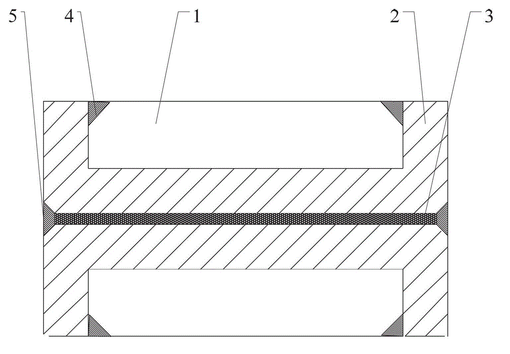
[0026] like figure 1 As shown, the preparation method of wear-resistant steel and carbon structural steel composite plate of the present invention comprises the following steps:

[0027] (1) Processed slab: process grooves on the upper part of the carbon structural steel plate 2 according to the size of the wear-resistant steel plate 1;

[0028] (2) Surface cleaning: the surface of the groove on the upper part of the carbon structural steel plate 2 and the wear-resistant steel plate 1 are sandblasted to remove surface rust and oxide layer, cleaned and dried;

[0029] (3) Making composite slabs: place the cleaned wear-resistant steel plate 1 in the groove on the upper part of the carbon structural steel plate 2, clamp it with a clamp and put it into a vacuum chamber, and evacuate until the air pressure is ≤1.0×10 -2MPa; then the groove periphery of the carbon structural steel plate 2 and the joint of the wear-resistant steel plate 1 are sealed and welded with an electron beam ...

Example Embodiment

[0035] Example 1

[0036] In this embodiment, the model of wear-resistant steel plate 1 is NM360, the size (thickness×width×length) is 10mm×1000mm×3000mm, and the quantity is 2 pieces, the model of carbon structural steel plate 2 is Q345, and the size (thickness×width×length) Length) is 50 mm × 1100mm × 3100mm, and the quantity is 2 pieces. Firstly, a groove (thickness × width × length) of 10 mm × 1000mm × 3000mm is processed on the upper part of the carbon structural steel plate 2, and the distance between the edge of the groove and the carbon The same-side edge of the plain structural steel plate 2 is 50 mm. Sandblasting is used to remove the rust and oxide layers of the wear-resistant steel plate 1 and the carbon structural steel 2, and the grain size of the iron sand used for sandblasting is ≤1mm; then the two steel plates are cleaned and dried.

[0037] Put a piece of wear-resistant steel plate 1 in the groove of a piece of carbon structural steel 2, and clamp it with a ...

Example Embodiment

[0042] Example 2

[0043] In this embodiment, the model of wear-resistant steel plate 1 is NM360, the size (thickness×width×length) is 25mm×1000mm×2500mm, and the quantity is 2 pieces, the model of carbon structural steel plate 2 is Q235, and the size (thickness×width×length) Length) is 50 mm × 1080mm × 2580mm, the quantity is 2 pieces, first process a groove (thickness × width × length) of 25mm × 1000mm × 2500mm on the upper part of the carbon structural steel plate 2, the distance between the edge of the groove and the carbon The same-side edge portion of the structural steel plate 2 is 40 mm. Sandblasting is used to remove the rust and oxide layers of the wear-resistant steel plate 1 and the carbon structural steel 2, and the grain size of the iron sand used for sandblasting is ≤1mm; then the two steel plates are cleaned and dried.

[0044] Put a piece of wear-resistant steel plate 1 in the groove of a piece of carbon structural steel 2, clamp it with a clamp, put it into ...


PUM

PropertyMeasurementUnit
Thicknessaaaaaaaaaa
Thicknessaaaaaaaaaa
Shear strengthaaaaaaaaaa

Abstract

The invention discloses a preparation method for wear-resistant steel and carbon structural steel composite plates. The method includes the steps: processing a groove on each carbon structural steel plate according to the size of each wear-resistant steel plate, and cleaning the surfaces of the grooves and the wear-resistant steel plates; placing the wear-resistant steel plates into the grooves correspondingly, placing the wear-resistant steel plates and the carbon structural steel plates into a vacuum chamber in a clamping manner, performing seal welding for the bonding positions of the peripheries of the grooves with the wear-resistant steel plates to form wear-resistant steel plate blanks, and spraying high-temperature anti-adhesion coating on the bottom surfaces of the carbon structural steel plates; stacking the bottom surfaces of the carbon structural steel plates sprayed with the high-temperature anti-adhesion coating in two composite plate blank groups in a relative bonding manner, placing into the vacuum chamber in a clamping manner, and performing seal welding for the peripheries of the bonding surfaces of the two composite plate blank groups to form a combined blank; placing the combined blank into a heating furnace for heating prior to rolling; and conveying the rolled combined blank onto a roller type quenching machine for quenching prior to trimming so that the two wear-resistant steel and carbon structural steel composite plates are obtained. The method is capable of decreasing probability of welding defects and improving interfacial strength of the composite plates without changing performances of base plate layers, and is high in production efficiency.

Description

technical field [0001] The invention belongs to the technical field of preparation of metal composite plates, and in particular relates to a method for preparing a composite plate of wear-resistant steel and carbon structural steel. Background technique [0002] Wear-resistant steel plates are widely used in mechanical products such as engineering, mining, construction, agriculture, cement production, ports, electric power and metallurgy that require high strength and high wear resistance under harsh working conditions. In terms of performance, wear-resistant steel generally only has high hardness and wear resistance, and its plasticity, toughness and welding performance are relatively poor, which restricts the application of wear-resistant steel in the machinery industry to a certain extent. In order to broaden the application range of wear-resistant steel plates and improve their performance, it is often necessary to combine wear-resistant steel plates with other steel pla...

Claims


Application Information

Patent Timeline
IPC IPC(8): B21B1/38B21B47/02B21B45/02B21B37/74
Inventor 杨奕汪荣蒋扬虎韩斌魏兵谭文刘洋汪水泽陈丽娟
Owner 武汉钢铁有限公司
Why Eureka
Try Eureka