Manufacturing method of high heat transfer efficiency radiators

A heat sink, high-efficiency technology, applied in the direction of cooling/ventilation/heating transformation, anodizing, etc., can solve the problems of unsatisfactory heat dissipation performance, high cost, temperature rise effect of computer or electronic components, etc.

Inactive Publication Date: 2013-01-16
陈世明
View PDF4 Cites 6 Cited by
  • Summary
  • Abstract
  • Description
  • Claims
  • Application Information

AI Technical Summary

Problems solved by technology

[0004] However, regarding the above-mentioned methods of improving heat transfer rate, whether it is the number of fins that can be planted or the forced convection blown by a fan, there is a limit, that is to say, the heat dissipation that a radiator of a specification can provide per unit time is with its rated limit
However, at present, the faster the processing speed of computers or electronic components, the greater the heat generated, which often exceeds the load of the radiator, thus causing the temperature rise effect of computers or electronic components, affecting their normal operation and service life
Also, in order to solve the above-mentioned problems, some manufacturers use water-cooled radiators or TEC (Thermo-Electric Cooler) technology to construct radiators. However, water-cooled radiators are not only bulky and expensive. High, there is also the lack of cooling water condensation or pipeline leakage, and the use of cooling chips is a heat dissipation component mainly built with a semiconductor process. The theoretical basis for cooling is the Peltier Effect. This is a kind of thermoelectric effect. After the cooling chip is powered on, the heat is transferred from the heat-absorbing end on one side to the heat-emitting end on the other side. The technology listed above is based on the First Law of Thermodynamics-Conservation of Energy), the cooling chip only transfers the heat to the other side through the thermoelectric effect of the chip, and then dissipates heat through the heat dissipation component on the other side, which is not only expensive, but also the heat dissipation performance is not as expected. , when the cooling chip cannot provide effective heat dissipation for the computer or electronic components, resulting in a temperature rise effect, further reducing the temperature difference between the heat-absorbing end and the exothermic end, and reducing the heat transfer efficiency, so its practicability is not high

Method used


Image

  • Manufacturing method of high heat transfer efficiency radiators
  • Manufacturing method of high heat transfer efficiency radiators
  • Manufacturing method of high heat transfer efficiency radiators

Examples


Embodiment Construction

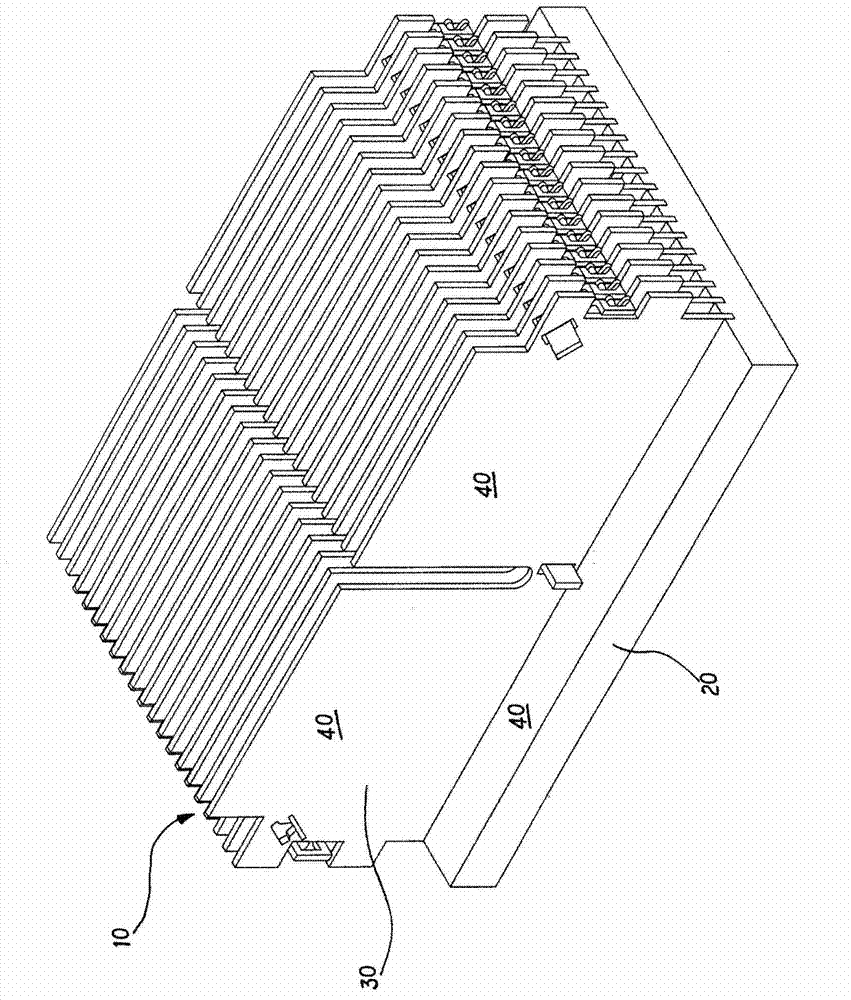
[0023] A method for making a high heat transfer efficiency radiator of the present invention, please refer to figure 1 As shown, the composition of the heat sink 10 includes a base 20. The base 20 can be rectangular, circular, geometric or irregular in shape and one side is attached to a heat source (not shown in the figure). The heat source includes but is not limited to an integrated circuit , chip or light-emitting diode module, the other side of the base 20 is combined with a plurality of fins 30, and the combination method can be welding, riveting, stamping or gluing with heat pipes, so that the fins 30 and the base 20 are closely integrated, and the heat source generates The heat is conducted to the fins 30 through the base 20 to dissipate heat;

[0024] According to Stefan-Boltzman Law (Stefan-Boltzman Law), it shows that at the absolute temperature T, the total radiation rate emitted from a black body (Black body) is Qb=AσT 4 , where A is the axonal area, and σ is the...


PUM


Abstract

The invention provides a manufacturing method of high heat transfer efficiency radiators, comprising the following steps: providing a plate-shaped or barrel-shaped base and a plurality of fins combined with the base, wherein the base and the fins are formed by aluminums; and forming an oxidation film layer capable of improving the thermal radiation emission rate of the base or/and fins on the surface of the base or/and fins through an anode processing technology, wherein the high heat transfer efficiency radiator further comprises a heat pipe; the heat energy of the base is rapidly transferred to the fins to radiate by menas of the heat pipe; or the treatment is performed at anodes of the fins by using a radiator type combined by the heat pipe and the fins to form the oxidation film layer. According to the characteristics, the radiator improves the heat transfer efficiency and simultaneously has the functions of beautiful appearance, easy identification and fouling resistance.

Description

[0001] This application is a divisional application with an application date of March 20, 2009, an application number of 200910129462.2, and an invention title of "Method for Manufacturing Radiators with High Heat Transfer Efficiency". technical field [0002] The present invention relates to a manufacturing method of a heat sink with high heat transfer efficiency, especially a heat sink applied to computers or electronic components, and through anodic treatment technology, the heat transfer efficiency is improved, and it is also beautiful and easy to identify and anti-fouling function. Background technique [0003] The heat sink of a general computer or electronic component is composed of a base attached to the heat source and fins combined with the base, or a heat pipe combined with the base and fins is further used to conduct the heat from the heat source to the base, Directly use fins or indirectly lead to fins through heat pipes to achieve heat dissipation performance. ...

Claims


Application Information

Patent Timeline
Patent Type & Authority Applications(China)
IPC IPC(8): C25D11/02C25D11/04H05K7/20
Inventor 陈世明
Owner 陈世明
Why Eureka
Try Eureka