Electroplated diamond wire saw sand-applying device

A technology for electroplating diamond and equipment, applied in electrolytic coatings, coatings, etc., can solve the problems of slow plating solution circulation, low current density, large space occupation, etc., to eliminate core wire asynchrony, high current density, and improve holding force. Effect

Inactive Publication Date: 2013-01-30
无锡超亚环保设备有限公司
View PDF5 Cites 24 Cited by
  • Summary
  • Abstract
  • Description
  • Claims
  • Application Information

AI Technical Summary

Problems solved by technology

[0021] The up and down roller type is much improved compared with the horizontal roller type, but due to the low electroplating current density and the core wire is wound on the conductive roller, the diamond powder on the side of the conductive roller is easy to fall off during the operation of the core wire;
[0022] 2. Low electroplating current density (related to anode distribution)
[0023] Due to the above three types of methods, because there is no metal anode around the core wire, or there are relatively few metal anodes, or the metal anode is far away from the core wire, the current density of the core wire under a certain electroplating voltage is relatively low during the electroplating process. Seriously affect the efficiency of electroplating and sanding;
[0024] 3. A large amount of diamond powder is required during production;
[0025] Due to the limitations of the sanding method and equipment, such as the buried sand method - a large amount of diamond micropowder must be used to bury the core wire in it, and the amount of micropowder can be imagined; and other suspension sanding methods, due to the need for conductive rollers and non-conductive rollers The conductive rollers are surrounded by several or even tens of turns, resulting in a large space occupation; even if the winding structure is directly placed in the floor tank for electroplating without using the mother and child tank structure, the volume of the plating tank is also large
[0026] 4. Defects in the way of winding the roll
[0027] The more turns around the rollers, the faster the electroplating and sanding speed, but the problems caused by this are more serious; the more turns between the electric rollers, the more complicated the threading before production, and the production process is due to The winding roller processing, installation accuracy and its own method make it easy to break the wire; resulting in immeasurable production risks;
[0028] 5. The circulation of the plating solution is relatively slow, which leads to the low concentration of cations around the core wire and cannot be replenished in time. In addition to the low plating efficiency, the plating layer is prone to hydrogen embrittlement; although there is a subsequent hydrogen drive process, there are still risks

Method used


Image

  • Electroplated diamond wire saw sand-applying device
  • Electroplated diamond wire saw sand-applying device

Examples


Embodiment Construction

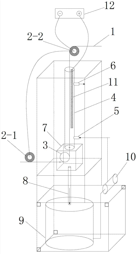
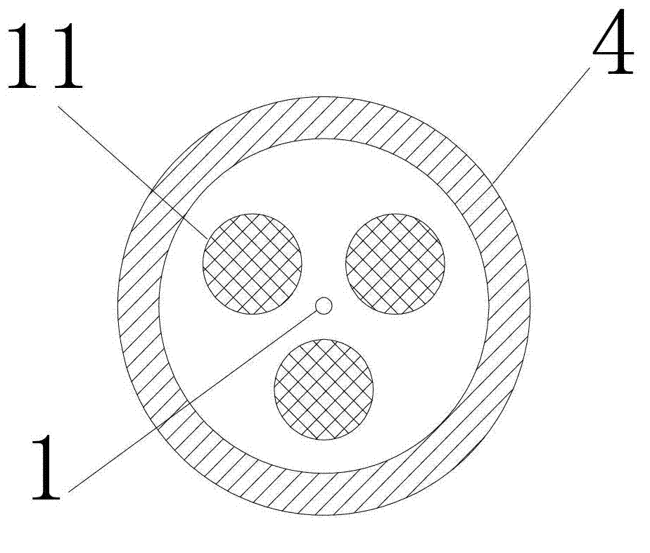
[0050] Such as figure 1 As shown, the present invention is an electroplating diamond wire saw sanding equipment, which is characterized in that the equipment is provided with a vertical tube type upper sand tank 4, a liquid return box 7, a plating solution mother tank 9, and a liquid return box 7 from top to bottom. The guide wheel 3 is fixed inside, and the core wire 1 is wound successively around the incoming conductive wheel 2-1 and the guide wheel 3 at the bottom of the vertical tube type upper sand tank 4, and then passed through the vertical tube type upper sand tank 4, and finally wound and set on the vertical tube type upper sand tank On the outgoing line conductive wheel 2-2 at the top of the slot 4, the incoming line conductive wheel 2-1 and the outgoing line conductive wheel 2-2 are connected in parallel to the negative pole of the electroplating power supply 12, and the core wire 1 in the vertical tube type upper sand tank 4 A metal anode 11 is arranged around, an...


PUM


Abstract

The invention discloses an electroplated diamond wire saw sand-applying device. The device sequentially comprises the components, from top to bottom: a vertical tubular sand-applying sub tank, a liquid-returning box, and a plating solution master tank. A guide wheel is fixed in the liquid-returning box. A core wire is sequentially wound on a wire-feeding conductive wheel on the bottom of the vertical tubular sand-applying sub tank and the guide wheel. The core wire then penetrates the vertical tubular sand-applying sub tank, and is finally wound on a wire-discharging conductive wheel on the top of the vertical tubular sand-applying sub tank. The wire-feeding conductive wheel and the wire-discharging conductive wheel are connected in parallel, and are then connected to the negative electrode of an electroplating power supply. Metal anodes are arranged around the core wire in the vertical tubular sand-applying sub tank. The metal anodes are connected with positive electrodes of the electroplating power supply. Through a water pump above the plating solution, the plating solution is lifted from the plating solution master tank into the vertical tubular sand-applying sub tank. With the device provided by the invention, sand-application of produced diamond wire is uniform and good. During the production process, current density is high, efficiency is high, internal stresses of the plating and the substrate are small, plating solution application amount is low, and wire breakage probability is low.

Description

technical field [0001] The invention relates to a sanding device for an electroplated diamond wire saw. Background technique [0002] Diamond wire saw, also known as diamond wire, refers to the use of electroplating process or resin bonding method to fix diamond abrasive on the wire. [0003] Electroplating diamond wire saw: A layer of metal (usually nickel or nickel-cobalt alloy) is deposited on the wire by electroplating, and diamond abrasives are consolidated in the metal. [0004] Diamond wire saw application fields: [0005] 1. Solar energy field: cutting of monocrystalline silicon rods or polycrystalline silicon ingots; slicing of silicon wafers. [0006] 2. LED field: sapphire ingot square cutting and slicing. [0007] 3. Other fields: magnetic materials such as neodymium magnets or ferrite magnets; silicon carbide and other difficult-to-cut materials, various substrates; crystal slices; ceramic cutting. [0008] Advantages of diamond wire saw cutting process: ...

Claims


Application Information

Patent Timeline
Patent Type & Authority Applications(China)
IPC IPC(8): C25D15/00
Inventor 张国瑞牛吉云
Owner 无锡超亚环保设备有限公司
Why Eureka
Try Eureka