
Lithium battery injection and formation vacuuming integrated device

A liquid injection and vacuum pumping technology for lithium batteries, which is applied in the manufacture of battery pack components, non-aqueous electrolyte batteries, and electrolyte batteries, can solve problems affecting battery quality, cumbersome process steps, and increased battery manufacturing costs, achieving increased Effects of battery capacity, shielding adverse effects, and improving cycle life

Inactive Publication Date: 2013-01-30
JIANGSU FRONT NEW ENERGY
View PDF6 Cites 10 Cited by
  • Summary
  • Abstract
  • Description
  • Claims
  • Application Information

AI Technical Summary

Problems solved by technology

In the existing lithium battery enterprises, the liquid injection and formation of the battery are almost carried out in separate processes. Since the electrolyte and water are prone to react, water control has become the top priority. Therefore, the environmental requirements of the battery workshops of various lithium battery manufacturers are compared. Strict, according to the formation method, the battery is divided into two types: vacuum type or air bag type. The environmental requirements for the liquid injection and formation process of the two are as follows. ≤-30°C in a drying room, the PP tube needs to be inserted and pulled out during the formation, which inevitably makes the inside of the battery come into contact with the outside world, so there are certain requirements for the temperature and humidity of the formation workshop, that is, the ambient temperature is 15°C to 35°C, and the humidity is ≤40 %; airbag type: open-mouth injection is used, and the requirements for the injection environment are more stringent. The temperature of the drying room is required to be 20±5°C, and the dew point is ≤-40°C. The influence of the battery, and the process steps are cumbersome, which not only increases the manufacturing cost of the battery cell, but also affects the quality of the battery

Method used


Image

  • Lithium battery injection and formation vacuuming integrated device

Examples


Embodiment Construction

[0010] The present invention will be further described in conjunction with the accompanying drawings.

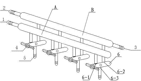
[0011] Referring to the attached drawing, the lithium battery liquid injection and formation vacuum integrated device is composed of the liquid injection pipeline A and the vacuum pipeline B in the double-row pipeline, the double-opening piston 6, the catheter 5 and the program-controlled part, and the left side of the A pipe is 1 is connected to the liquid storage tank, 2 on the left side of tube B is connected to the vacuum pump, and the battery is vacuumed during formation, and 3 on the right side of tube B is connected to the vacuum gauge for vacuum display. There is a glyph handle 4 on one side of the double-opening piston 6, and the two ends of the handle are respectively marked with "Z" and "C". The 6-3 port is alternately connected with the 6-1 and 6-2 ports or isolated simultaneously, and the 6-3 port is used to connect with the battery valve port. The specific ope...


PUM


Abstract

The invention discloses a lithium battery injection and formation vacuuming integrated device, which is mainly formed by an injection pipeline, a vacuuming pipeline, double-open pistons, a conduit and a program control part, wherein the injection pipeline and the vacuuming pipeline are arranged in two rows, and four to eight double-open pistons are connected onto the injection pipeline and the vacuuming pipeline which are mutually independent. The lithium battery injection and formation vacuuming integrated device is used for flexibly packaged lithium battery injection and formation vacuuming, and can be operated automatically; the working processes are simplified, electrolyte is prevented from being directly contacted with air, and the influence of water on performances of a battery is reduced; and simultaneously, due to formation vacuuming, air generated in the battery during a charging process can be thoroughly discharged, an insulation area is eliminated, the capacity of the battery is improved, and the cycle life of the battery is prolonged.

Description

technical field [0001] The invention relates to production equipment for flexible packaging lithium-ion batteries, in particular to an integrated device for liquid injection, formation and vacuuming of lithium batteries. Background technique [0002] In recent years, due to the advantages of high working voltage, high energy density, long cycle life, no memory effect, no environmental pollution, and high current charging and discharging, lithium-ion batteries have been widely used in portable electronic products, electric toys, electric vehicles, and large power plants. The fields of power supply and energy storage have been developed by leaps and bounds. [0003] The liquid injection and chemical formation process play a vital role in the production process of lithium batteries, which determine various performances such as the film formation status and cycle life of the battery. In the existing lithium battery enterprises, the liquid injection and formation of the batter...

Claims


Application Information

Patent Timeline
Patent Type & Authority Applications(China)
IPC IPC(8): H01M2/36H01M10/058
CPCY02E60/12Y02E60/10Y02P70/50
Inventor 司晓影王青熊坚吴晓东
Owner JIANGSU FRONT NEW ENERGY
Learn More