Method for simultaneously desulfurizing and denitrating flue gas

A technology for desulfurization, denitrification, and flue gas, which is applied in the fields of chemical technology and gas pollutant treatment, can solve problems that have not been reported, and achieve the effect of simple operation, high efficiency, and large amount of flue gas treatment

Active Publication Date: 2013-02-06
PEKING UNIV
View PDF5 Cites 30 Cited by
  • Summary
  • Abstract
  • Description
  • Claims
  • Application Information

AI Technical Summary

Problems solved by technology
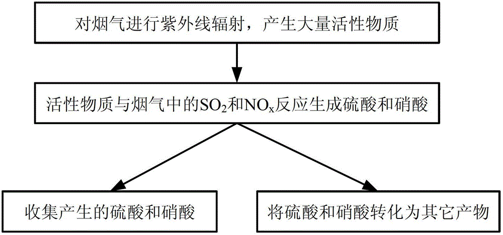
At present, the simultaneous treatment of SO in flue gas by vacuum ultraviolet irradiation 2 , NO and NO 2 research has not yet been reported

Method used


Image

  • Method for simultaneously desulfurizing and denitrating flue gas
  • Method for simultaneously desulfurizing and denitrating flue gas
  • Method for simultaneously desulfurizing and denitrating flue gas

Examples


Embodiment 1

[0030] Example 1: Dynamic SO 2 and NO x (NO+NO 2 ) removal

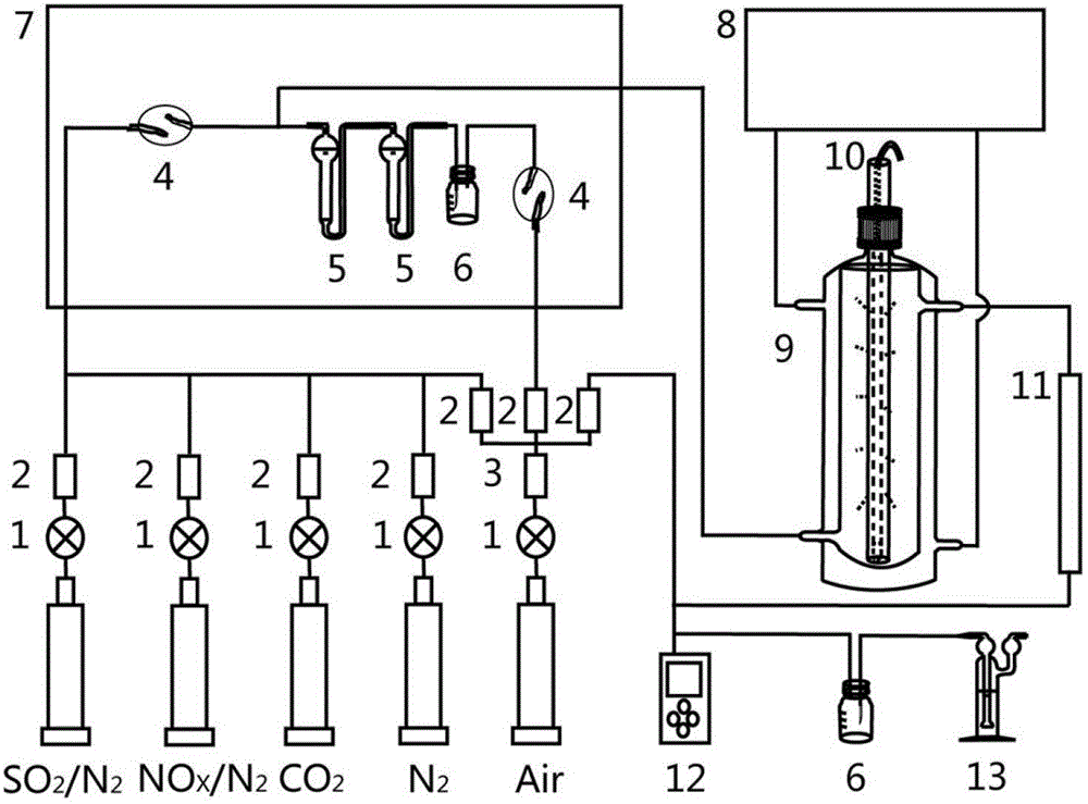
[0031] figure 2 It is a schematic structural diagram of simultaneous desulfurization and denitrification equipment, in which the temperature of the oven 7 and the constant temperature water bath 8 is set at 60-90°C to simulate the temperature range of the actual exhaust gas. As shown in the figure, with N 2 , air, CO 2 , NO x / N 2 , SO 2 / N 2 Gas and H 2 O synthetic simulated flue gas, SO 2 and NO x The concentrations are 800ppm and 350ppm respectively, O 2 Concentration 8%, CO 2 The concentration is 10%, the water vapor content generated by saturated water vapor accounts for 8% of the final simulated flue gas volume, and the rest is N 2 . The mixed simulated flue gas enters the oven 7 at a flow rate of 500 sccm, and the temperature of the simulated flue gas rises to 60°C after passing through the oven 7 and the double-layer water-bath photoreactor 9, and the outlet of the double-layer water-bath phot...

Embodiment 2

[0033] Example 2: Dynamic SO 2 removal of

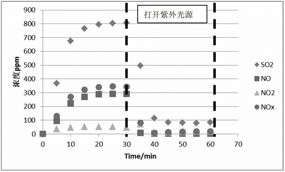
[0034] Such as figure 2 shown, use N 2 , air, CO 2 , SO 2 / N 2 Gas and H 2 O synthetic simulated flue gas, SO in the synthetic simulated flue gas 2 The content is 800ppm, O 2 Concentration 8%, CO 2 The concentration is 10%, and the water vapor content generated by saturated water vapor accounts for 8% of the final simulated flue gas volume. The simulated flue gas flow rate is 500 sccm, and the temperature is 60°C. Use a flue gas detector analyzer to monitor SO in the outlet flue gas 2 content changes. Such as Figure 4 As shown, in the process of 30min ultraviolet irradiation, SO 2 The removal rate reaches 90%, achieving the purpose of flue gas desulfurization, and the final main product is sulfuric acid.

Embodiment 3

[0035] Embodiment 3: Dynamic NO, NO 2 take off

[0036] Such as figure 2 shown, use N 2 , air, CO 2 , NO x / N 2 Gas and H 2 O synthetic simulated flue gas, NOx (NO+NO 2 ) content is 350ppm, O 2 Concentration 8%, CO 2 The concentration is 10%, the water vapor content generated by saturated water vapor accounts for 8% of the final simulated flue gas volume, the simulated flue gas flow rate is 500 sccm, and the temperature is 60°C. Use a flue gas analyzer to monitor NO and NO in the flue gas at the outlet 2 content changes. Such as Figure 5 As shown, in the process of 30min ultraviolet irradiation, NOx (NO+NO 2 ) The removal rate reaches 95%. To achieve the purpose of flue gas denitrification, the final main product is nitric acid.


PUM


Abstract

The invention provides a method for simultaneously desulfurizing and denitrating flue gas. The method comprises the step that: a large number of active materials produced by the flue gas under ultraviolet radiation are reacted with SO2 and NOx in the flue gas so as to produce stable sulfuric acid and nitric acid which are important industrial products. The two products can be collected by an acid mist removing device, or ammonia can be introduced into the two products to produce ammonium sulfate and ammonium nitrate which are important chemical fertilizers, or calcium carbonate is sprayed into the two products to produce calcium sulfate and calcium nitrate; and then, SO2 and NOx in the flue gas are removed from the flue gas to be converted into the products with the industrial or agricultural value. The method for simultaneously desulfurizing and denitrating the flue gas is suitable for desulfurizing and denitrating the flue gas of large newly-built boilers, or reforming and applying built burning equipment, and can realize the effect of simultaneously removing SO2 and NOx.

Description

technical field [0001] The invention belongs to the technical fields of chemical technology and gas pollutant treatment, and in particular relates to a method for simultaneous desulfurization and denitrification of flue gas. Background technique [0002] my country's SO in recent years 2 and NO x The situation of increasing emissions is severe, and the strengthening of SO 2 and NO x Pollutant emission control is very important. According to the "Twelfth Five-Year Plan" SO 2 and NO x Reducing the 8% and 10% binding indicators and the more stringent "Emission Standards of Air Pollutants for Thermal Power Plants" (GB13223-2011), the future trend of flue gas control will be simultaneous efficient desulfurization and denitrification. [0003] SO 2 and NO x At the same time, efficient removal is an important and difficult point of flue gas treatment. The most widely used desulfurization and denitrification integrated equipment is not a simultaneous treatment in the strict ...

Claims


Application Information

Patent Timeline
Patent Type & Authority Applications(China)
IPC IPC(8): B01D53/74B01D53/60
CPCY02A50/20
Inventor 尚静叶俊辉朱彤
Owner PEKING UNIV
Why Eureka
Try Eureka