Helical multi-gap high-frequency resonance device and bunching and accelerating method
A high-frequency resonance and multi-gap technology, applied in accelerators, electrical components, etc., can solve problems such as difficulty, insufficient electromagnetic analysis, and low operating frequency, and achieve the effect of improving efficiency and effect
- Summary
- Abstract
- Description
- Claims
- Application Information
AI Technical Summary
Problems solved by technology
Method used
Image
Examples
Embodiment 1
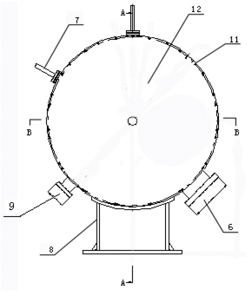
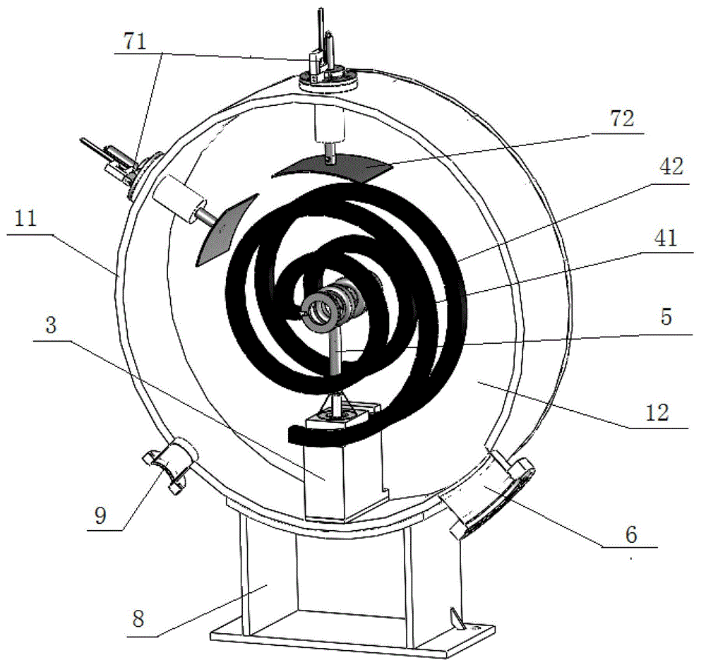
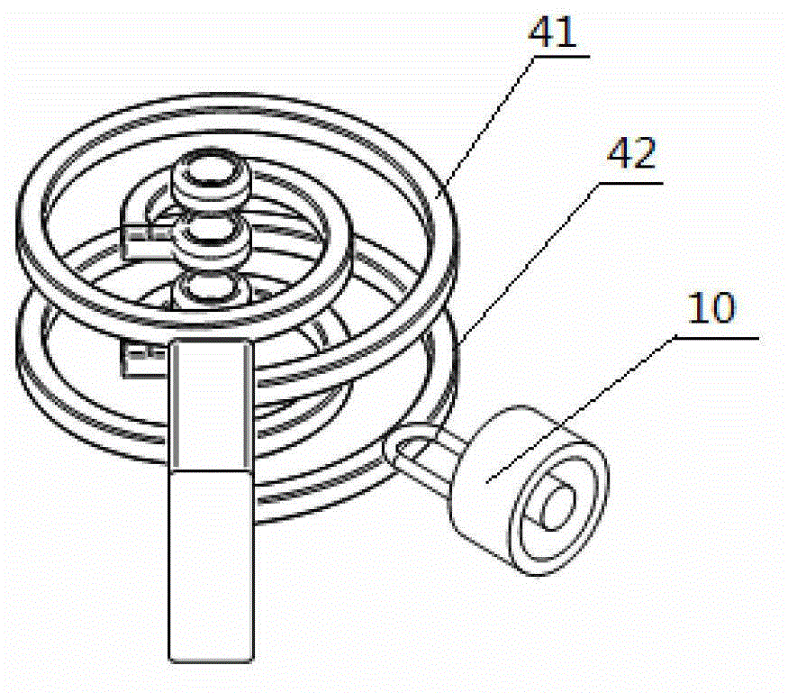
[0034] Example 1: see figure 1 , figure 2 , image 3 , Figure 4 , Figure 5As shown, a spiral multi-gap high-frequency resonance device includes a cavity on which a coupler bracket 6 is arranged. The cavity is composed of a cylindrical outer wall 11 and two circular side walls 12, Cylindrical outer wall 11 and two circular sidewalls 12 have surrounded airtight cavity, and the center of described two circular sidewalls 12 is provided with first drift tube 21 and the 5th drift tube 25, in cavity There is also a support seat 3 inside, the support seat 3 supports the second drift tube 22 and the fourth drift tube 24 in the cavity through the first helical arm 41 and the second helical arm 42, and the support seat 3 is also provided with There is a support rod 5, a third drift tube 23 is arranged on the top of the support rod 5, the first drift tube 21, the second drift tube 22, the third drift tube 23, the fourth drift tube 24, the fifth drift tube 25 coaxially arranged, th...
Embodiment 2
[0038] Embodiment 2: as Image 6 As shown, the present invention also provides a bunching method of the spiral multi-gap high-frequency resonance device: comprising the following steps,
[0039] (1) Resonance: The power source injects power into the spiral multi-gap high-frequency resonance device. When the power source is consistent with the power of the spiral multi-gap high-frequency resonance device, the power source can excite the spiral multi-gap high-frequency resonance device. In the cavity of the resonance device, the electromagnetic field is established and starts to resonate;
[0040] (2) Bunching: When the high-frequency voltage of the control power source is at zero phase, the central particle in the cavity of the spiral multi-gap high-frequency resonance device just reaches the gap between the first drift tubes; at this time, The particles earlier than the central particle are affected by the negative voltage and start to decelerate; while the particles arriving...
Embodiment 3
[0041] Embodiment 3: the same as Embodiment 1, the difference is that it also includes the following steps:
[0042] (3) After the particles reach the first drift tube gap and are bunched, since the distance between the first drift tube gap is half the wavelength of the resonance frequency, the entire high-frequency field is distributed in the second drift tube gap and the third drift tube gap. The drift tube gap and the fourth drift tube gap are all 180° out of phase; when the particle enters the second drift tube, the particle is shielded by the drift tube wall and is not affected by the electric field. When it reaches the second drift tube gap, due to the electric field After going through 180°, return to the original -180°, and reach the zero phase again. At this time, the particles converge again, and so on. Since the time of particle drift corresponds to the conversion time of the electric field, the particles pass through the third drift in turn. The tube gap and the fo...
PUM
 Abstract
Description
Claims
Application Information
 - R&D
- Intellectual Property
- Life Sciences
- Materials
- Tech Scout
- Unparalleled Data Quality
- Higher Quality Content
- 60% Fewer Hallucinations
Browse by: Latest US Patents, China's latest patents, Technical Efficacy Thesaurus, Application Domain, Technology Topic, Popular Technical Reports.
© 2025 PatSnap. All rights reserved.Legal|Privacy policy|Modern Slavery Act Transparency Statement|Sitemap|About US| Contact US: help@patsnap.com


