
VCSEL (vertical cavity surface emitting laser)-based low-power-consumption gas detection method and device

A technology of gas detection and low power consumption, which is applied in the field of optical fiber sensing, can solve the problems of high power consumption of TEC controllers, difficulties in implementing sensors, and high power consumption of sensors, so as to improve accuracy, simple and reliable methods, and promote development Effect

Active Publication Date: 2013-03-13
SHANDONG MICRO PHOTOGRAPHIC ELECTRONICS
View PDF3 Cites 22 Cited by
  • Summary
  • Abstract
  • Description
  • Claims
  • Application Information

AI Technical Summary

Problems solved by technology

However, in the method described, the DFB laser or the VCSEL laser requires precise temperature control, and the power consumption of the TEC controller is very large, so that the power consumption of this type of sensor is generally large, especially the starting current of the instrument is very large, Some even reach more than 500mAs, which makes it difficult for this type of sensor to meet the requirements of intrinsically safe parameters in coal mines, which is not conducive to direct online use with existing mining equipment such as base stations
This is a fatal shortcoming that prevents the popularization and use of this type of instrument in coal mines
[0004] The square spectral absorption method described in the Chinese patent "Gas detection method and gas detection device" requires precise temperature control of the light source when measuring gas. Since the light source is controlled by TEC, the power consumption of this measurement method is particularly large.

Method used


Image

  • VCSEL (vertical cavity surface emitting laser)-based low-power-consumption gas detection method and device
  • VCSEL (vertical cavity surface emitting laser)-based low-power-consumption gas detection method and device
  • VCSEL (vertical cavity surface emitting laser)-based low-power-consumption gas detection method and device

Examples


Embodiment Construction

[0034] Now take methane as an example, and cooperate with the accompanying drawing of detection to do the following detailed description to the specific embodiment of the present invention:

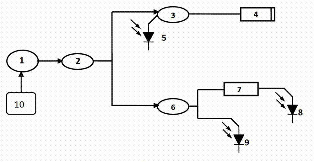
[0035] A VCSEL-based low-power gas detection device, including a temperature detection device 10, a VCSEL laser 1, an optical path assembly, an optical fiber sensing probe 4, a reference probe 7, a photoelectric detector, and a power reference detection device; the optical path assembly includes a branch A splitter 2 and a coupler; the temperature detection device 10 is connected to the VCSEL laser 1, and the VCSEL laser 1 is connected to the splitter 2 of the optical path assembly, and the splitter 2 is connected to the input end of the first coupler 3 and the second The input end of the coupler 6, the output end of the first coupler 3 is connected to the optical fiber sensing probe 4, and the return end of the first coupler 3 is connected to the first photodetector 5; The output end is ...


PUM


Abstract

The invention discloses a VCSEL (vertical cavity surface emitting laser)-based low-power-consumption gas detection method and device. The method comprises the following steps that: a microprocessor controls a sawtooth wave current driving circuit to drive a VCSEL to generate light with specified wavelength in the first step; the light emitted from the VCSEL reaches an optical fiber sensing probe and a reference air chamber through a light path; and an optical signal with concentration information enters a photoelectric conversion circuit and is converted into a corresponding analog voltage signal by the photoelectric conversion circuit, the analog voltage signal is converted into a digital voltage signal which can be identified by the microprocessor through an analog / digital (A / D) conversion circuit, a temperature measurement circuit transmits a measured environment temperature value to the microprocessor, and thus the microprocessor obtains the wavelength of the light emitted from the VCSEL in case of a given driving current and calculates a field gas concentration signal according to a Beer-Lambert law. The method has the advantage of implementing the gas concentration detection at low power consumption.

Description

technical field [0001] The invention relates to the field of optical fiber sensing, in particular to a VCSEL-based low-power gas detection device and method. Background technique [0002] With the continuous development of industrial and agricultural production technology, timely and accurate monitoring of various gases has become an important problem that needs to be solved urgently in industries such as petroleum, chemical industry, electric power, and coal mine safety. At the same time, with the continuous improvement of people's living standards, human beings have higher and higher requirements for the ecological environment. It is urgent to pay attention to environmental protection and monitor and control the environment while developing. For this reason, the development of gas sensors has become an important topic in the field of sensing today. [0003] Optical fiber gas detection technology, which appeared in the 1980s, is a new type of gas detection method. It has t...

Claims


Application Information

Patent Timeline
IPC IPC(8): G01N21/39
CPCG01N21/39G01N21/3504G01N2021/399H01S5/06213H01S5/0622H01S5/183
Inventor 李艳芳刘统玉魏玉宾王昌赵燕杰张婷婷赵维凇
Owner SHANDONG MICRO PHOTOGRAPHIC ELECTRONICS
Learn More