Universal bridge cast-in-place support

A general-purpose, bridge technology, applied in the direction of bridges, bridge construction, erection/assembly of bridges, etc., can solve the problems of insufficient local stress distribution, damage to the integrity and integrity of materials, and inconvenient transportation of large components. , to achieve the effect of flexible assembly, convenient transportation and light weight

Inactive Publication Date: 2013-03-27
曹新恒
View PDF5 Cites 21 Cited by
  • Summary
  • Abstract
  • Description
  • Claims
  • Application Information

AI Technical Summary

Problems solved by technology

Among them, the mobile formwork cast-in-place construction has a high degree of mechanization and does not need to consider the ground conditions, but it is only suitable for specific bridge-type cast-in-place construction. It has certain requirements for the scale of the project, and it is difficult to assemble and disassemble, and it is inconvenient to transport large components. ;For the full hall support, although it is used in all bridge types, the erection of the support is labor-intensive and time-consuming. Although the upper load has been shared by the support poles, the local area stress under the poles still cannot be effectively dispersed. The bearing cap

Method used


Image

  • Universal bridge cast-in-place support
  • Universal bridge cast-in-place support
  • Universal bridge cast-in-place support

Examples


Embodiment approach 1

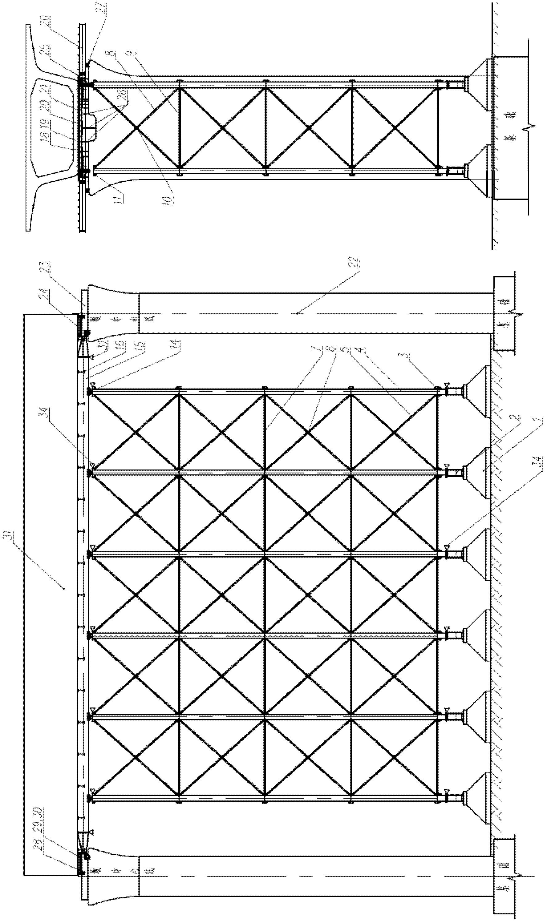
[0034] Implementation mode 1: The explanation is based on the cast-in-place construction of the 32.6m double-track simply supported box girder of the railway passenger dedicated line. Such as figure 1 Shown is a working state diagram of a universal cast-in-situ support for a bridge with a pier height of 20m or more. The specific assembly method is as follows:

[0035] 1. First select the required combination of concrete-filled steel tube column bottom section 3 and concrete-filled steel tube column 4 based on the height of the pier and the bottom curve of the beam;

[0036] 2. The foundation within a certain range at the bottom of the beam should be properly treated according to the specific situation. It is recommended that the foundation treatment plan is mainly digging down, and it is not recommended to fill or replace, because the support system has a good ability to adapt to the height difference of the foundation. Therefore, it is not necessary to require the foundation of th...

Embodiment approach 2

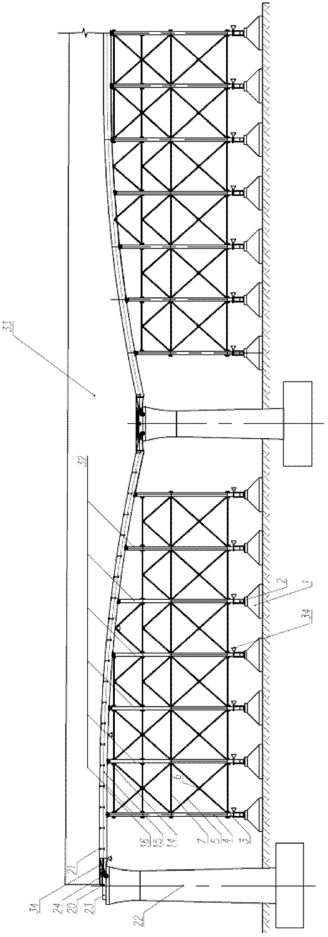
[0060] Embodiment 2: Here, the integral cast-in-place continuous beam with variable cross-section is taken as the object of description, and the specific application of the patent of the present invention is explained. Such as figure 2 The working state diagram of the universal bridge cast-in-place support of the present invention is shown for a continuous beam. The specific assembling method is the same as the method in the first embodiment. The characteristic is that the curve of the bottom of the beam changes so that the elevation of the bottom of the beam is not uniform, which requires more The adjustment section or a special column specially customized to adapt to the elevation of the bottom of the beam; and the dismantling method of the bracket is exactly the same as that described in the first embodiment.


PUM


Abstract

The invention relates to a cast-in-place support platform for bridge cast-in-place construction, and the platform is characterized by consisting of a movable seat, a hydraulic jack, a steel pipe concrete vertical column, stable tie bars on a longitudinal surface, a horizontal surface and a plane, a spherical hinge support, a support primary beam, a support secondary beam, a reinforcing diagonal rod, a distribution rib, a large steel mould at the bottom of the beam, a support and pier top fixed connecting system, a pier top crossbeam, a partial template of a pier tope, a pier top large tonnage hydraulic jack, an undercarriage hoist or a chain block in the beam, an undercarriage steel cable and the like; all the components are spliced detachably and interchangeably; the connection of all the components is mainly realized through bolts; and the cast-in-place construction of a bridge can be carried out after a cast-in-place support is assembled according to the actual situation on the site and the beam body template is arranged on the support. The universal bridge cast-in-place support has the biggest characteristics of good practicality, high standard degree, high load bearing capability of the support system, low requirement on the load bearing capability of a foundation, settlement monitoring and automatic compensation functions; and is applicable to the cast-in-place construction of simple support beams, continuous beams and arch bridges; has few assembled and disassembled parts and no components with large sizes after being disassembled, is convenient to transport, is the support equipment for bridge cast-in-place construction with the highest standardization level and the best universality so far, and can significantly shorten the construction period and save the cost.

Description

Technical Field: [0001] The field of bridge original cast-in-place construction machinery in civil construction of the patent of the invention Background technique: [0002] In the construction of the bridge, the construction method of the bridge can be divided into two major types of construction methods: prefabricated erection and cast-in-place construction. In actual production, it is usually selected according to the actual situation of the site, but in most cases due to site conditions or projects It is more suitable to adopt the cast-in-place construction method for bridge construction. At present, in-situ cast-in-place construction mainly includes the following: 1) Movable formwork cast-in-place construction, which is currently the most advanced bridge cast-in-place construction method; 2) Full house support cast-in-place construction method; 3) Steel pipe pile support+ Bailey frame + bowl fastener cast-in-place construction. Among them, the mobile formwork cast-in-place...

Claims


Application Information

Patent Timeline
IPC IPC(8): E01D21/00
Inventor 曹新恒
Owner 曹新恒
Why Eureka
Try Eureka