Device and method for measuring static rigidity of rolling linear guide rail pair

A technology of a linear guide rail pair and a measuring device, applied in the field of measurement, can solve the problems of influence of measurement accuracy, small load range, inconvenient operation, etc., and achieve the effects of good self-locking performance, improved measurement efficiency, and easy installation and adjustment.

Active Publication Date: 2013-04-03
NANJING UNIV OF SCI & TECH
View PDF6 Cites 26 Cited by
  • Summary
  • Abstract
  • Description
  • Claims
  • Application Information

AI Technical Summary

Problems solved by technology

[0004] After searching the literature of the existing technology, it was found that the rolling linear guide rail pair static stiffness test machine designed by Fang Jian and others of Huazhong University of Science and Technology in 2006 was loaded by a hydraulic system, and the static stiffness was generated by the data collected by the force sensor and the inductance micrometer. Stiffness curve, different types of guide rails are installed through T-shaped slots, and the loading hydraulic cylinder can adjust the loading position left and right through the ball screw; the maximum loading load of this testing machine is 30KN, and the loading load range is small, which cannot meet the static stiffness measurement of large-sized guide rail pairs. Yes, the hydraulic loading system has high requirements for constant pressure control. When loading, the position of the hydraulic cylinder needs to be adjusted through the screw to load the guide rail pair. The operation is inconvenient, and there is only a device and method for vertical loading
In addition, the Chinese Invention Patent Publication No. CN102279100A, n

Method used


Image

  • Device and method for measuring static rigidity of rolling linear guide rail pair
  • Device and method for measuring static rigidity of rolling linear guide rail pair
  • Device and method for measuring static rigidity of rolling linear guide rail pair

Examples


Embodiment Construction

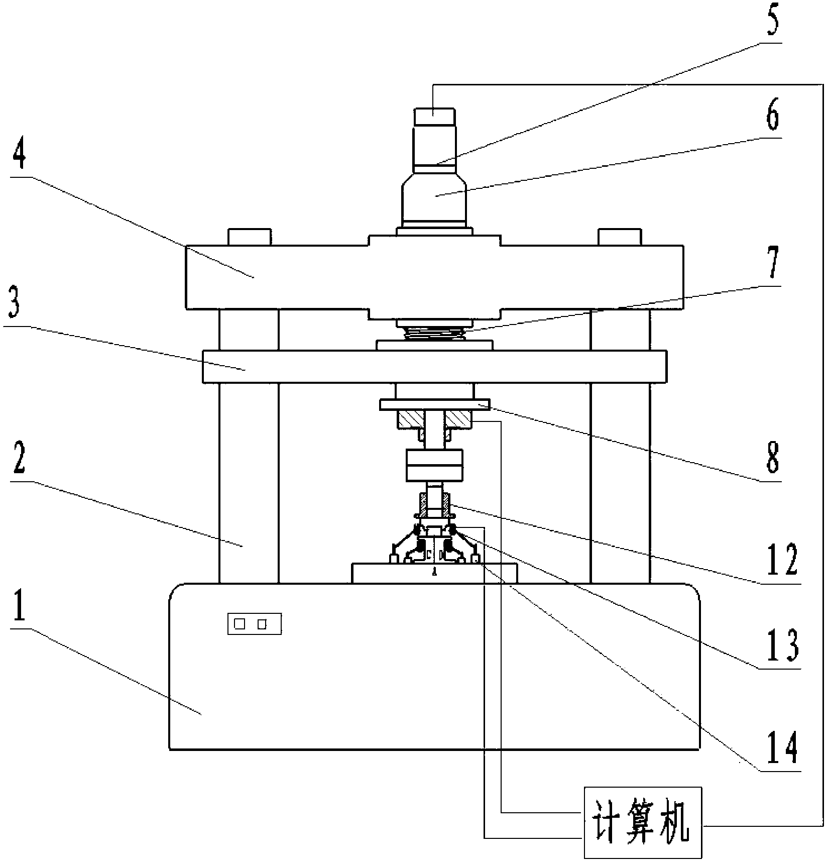
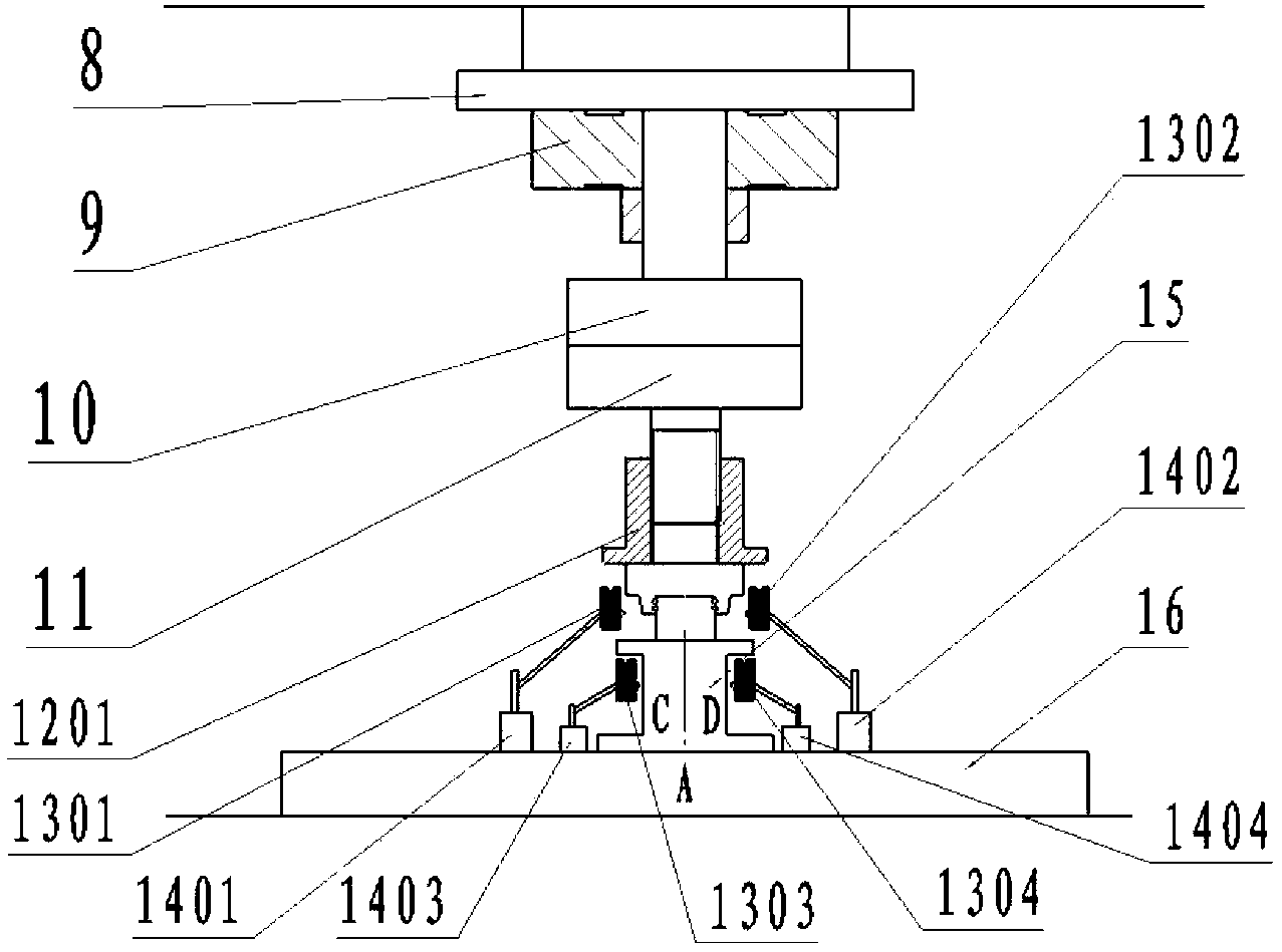
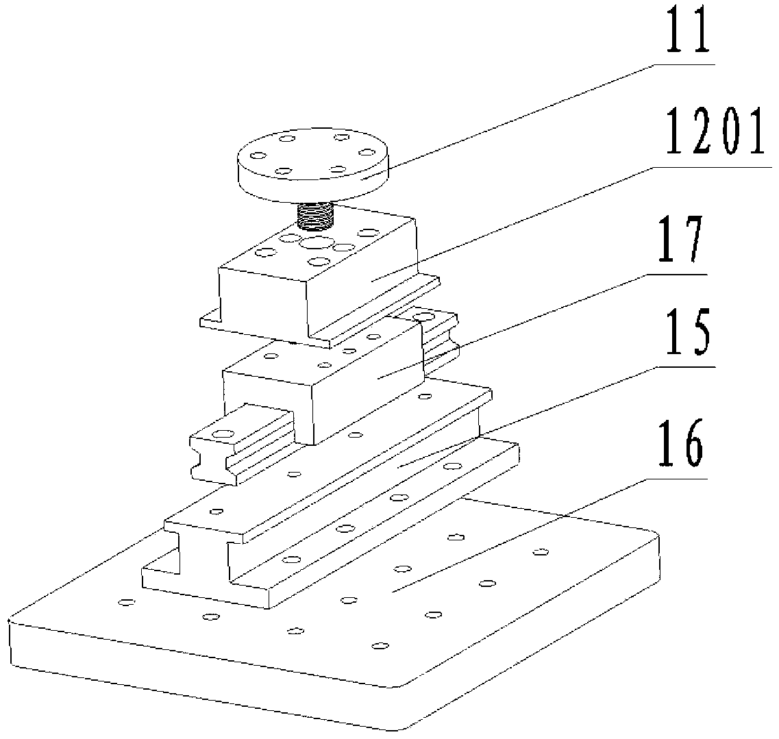
[0016] The invention uses a servo motor to drive a trapezoidal screw to drive the loading nut to load the rolling linear guide rail pair. By changing the installation position of the guide rail pair and the type of fixture on the guide rail, three loading methods can be performed on the guide rail pair: vertical, deflection and pitch loading. The force sensor and the laser displacement sensor sample the load and deformation of the tested guide rail pair respectively. The force sensor is fixed on the loading nut and can rise and fall with it. The center position of the laser displacement sensor and the corresponding measurement of different loading methods Points are aligned vertically. By processing the collected load and displacement data, the static stiffness curve of the rolling linear guide can be drawn, so as to realize the experimental measurement of the static stiffness of the rolling linear guide, and the load range of the measurement is large, the versatility is strong...


PUM


Abstract

The invention discloses a device and a method for measuring static rigidity of a rolling linear guide rail pair. A servo motor is used for driving a ladder-shaped lead screw to drive a loading nut to load the rolling linear guide rail pair. Three loading methods of vertical loading, deflecting loading and pitching loading can be adopted on the guide rail pair by changing installation positions of the guide rail pair and the type of an upper clamp of the guide rail. Measurement points, which correspond to different loading methods respectively, are distributed on the upper clamp and a lower clamp of the guide rail, and are used for determining deformation displacement of the guide rail pair when the guide rail pair is loaded. According to the device and the method for measuring the static rigidity of the rolling linear guide rail pair, automatic measurements of vertical static rigidity, deflecting static rigidity and pitching static rigidity of the rolling linear guide rail pair are achieved, a loaded load is high, measurement accuracy is high, and needs for different loading methods of different guide rail series can be satisfied.

Description

technical field [0001] The invention belongs to the technical field of measurement, in particular to a device and method for measuring the static stiffness of a rolling linear guide pair. Background technique [0002] Rolling linear guide rails are generally composed of guide rails, sliders, reversers, rolling elements and cages. It is a rolling support for relative reciprocating linear motion. The sliding contact, and the rolling element can achieve infinite circulation in the raceway and the slider with the help of the reverser. The rolling linear guide pair has the advantages of small friction coefficient, high running accuracy, no crawling, wear resistance, high rigidity, and small thermal deformation, and is widely used as a guide component for high-precision CNC machine tools and machining centers. [0003] Static stiffness is an important index that affects the performance and bearing capacity of rolling functional parts, and is the basic requirement for rolling line...

Claims


Application Information

Patent Timeline
IPC IPC(8): G01M5/00G01B11/02
Inventor 冯虎田王禹林衡豪陶卫军欧屹徐凤翔蔡理李隆
Owner NANJING UNIV OF SCI & TECH
Why Eureka
Try Eureka