Transformerless hybrid active power amplifier and implementation and control methods thereof

A technology of power filter and passive filter, applied in active power filter, harmonic reduction device, AC network to reduce harmonic/ripple, etc., can solve the problem of high system cost and capacity, high cost, and inability to absorb active power etc.

Inactive Publication Date: 2014-12-31
曹一家
View PDF4 Cites 0 Cited by
  • Summary
  • Abstract
  • Description
  • Claims
  • Application Information

AI Technical Summary

Problems solved by technology

Among them 1) Injection resonant hybrid active power filter, the injection branch is composed of passive filter and fundamental resonant circuit, and the active power filter is connected to the injection branch through a coupling transformer, since the fundamental wave voltage of the injection point is 0, the active power filter cannot absorb the active power to maintain its own work, and an additional low-voltage rectification device is required to maintain the DC voltage of the active power filter, which makes the system structure complex, large in size and high in cost; 2) Inductor and capacitor series hybrid In the active power filter topology, the voltage source inverter is connected in series with the filter inductor and capacitor to the coupling point of the public grid. All the reactive power compensation current and harmonic compensation current of the system must be provided by the active power filter. This leads to high rated current, high cost and poor reliability of the active power filter; 3) In the injection hybrid active power filter composed of inductors and capacitors, the passive branch circuit composed of inductors and capacitors provides reactive power compensation , the reactive current does not flow through the active power filter, and the active power filter only compensates the harmonic current. waves are compensated by active power filters, the cost and capacity of the system are still high

Method used


Image

  • Transformerless hybrid active power amplifier and implementation and control methods thereof
  • Transformerless hybrid active power amplifier and implementation and control methods thereof
  • Transformerless hybrid active power amplifier and implementation and control methods thereof

Examples


Embodiment 1

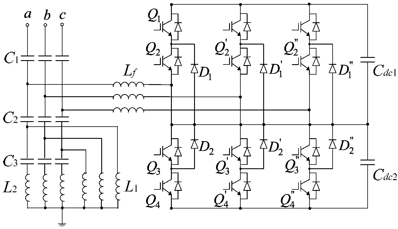
[0052] The present invention proposes a transformerless hybrid active power filter topology, such as figure 1 As shown, the transformerless injection hybrid three-level active power filter is composed of an improved double-tuned passive power filter and a diode-clamped three-level active power filter. Among them, the new double-tuned passive power filter consists of capacitor C 1 、C 2 、C 3 , L 1 , L 2 composition, the active power filter is connected in parallel with the injection capacitor C 1 after the point. The branch of the active power filter consists of a filter inductor L f , power module, DC capacitor C dc1 and C dc2 constitute. The power module is a three-level inverter module, which consists of IGBTQ 1 ~Q 4 , Q ′ 1~Q′ 4 , Q″ 1 ~Q″ 4 , clamping diode D 1 ~D 2 , D' 1 ~D' 2 , D″ 1 ~D″ 2 constitute.

[0053] Passive branch capacitance C 1 and C 2 Realize system reactive power compensation, and form a voltage divider circuit, capacitor C 1 To wi...


PUM


Abstract

The invention discloses a transformerless hybrid active power amplifier and implementation and control methods thereof. The transformerless hybrid active power amplifier comprises a double-turned passive filter and a diode-clamped active filter. The diode-clamped active filter is a tri-level inverter. The double-turned passive filter comprises three passive filter branches connected with phases A, B and C of a power grid respectively. Each passive filter branch comprises an impregnated capacitor (C1), a divider capacitor (C2), a parallel capacitor (C3), a first inductor (L1) and a second inductor (L2). Impregnation points of the three passive filter branches are connected with three terminals on the alternating-current side of the tri-level inverter through three output inductors (L) respectively. The transformerless hybrid active power amplifier features both low cost of a PPF (passive power filter) and excellent filtering and dynamic performance of an APF (active power filter), is easy to implement and is effective in filtering.

Description

technical field [0001] The invention belongs to the technical field of harmonic suppression and reactive power compensation in electric power systems, and relates to a transformerless hybrid active power filter and its realization method and control method. Background technique [0002] At present, the wide application of power electronic devices in power systems has brought power quality problems such as voltage flicker, reactive power shortage, and harmonic pollution to the power grid. In order to prevent major accidents caused by the above power quality problems, it is necessary to install advanced harmonic suppression and reactive power compensation devices in the distribution network. [0003] The above problems can be solved by passive filters or active power filters. Passive power filters use the resonance characteristics of inductance and capacitance elements to form harmonic low-impedance branches, which have the advantages of low cost and mature technology, but ha...

Claims


Application Information

Patent Timeline
Patent Type & Authority Patents(China)
IPC IPC(8): H02J3/01H02J3/18
CPCY02E40/40Y02E40/22Y02E40/20
Inventor 曹一家于晶荣陈岗曹小明
Owner 曹一家
Why Eureka
Try Eureka