Roll for hot-rolling apparatus and process for producing same
A manufacturing method and equipment technology, applied in the direction of rolls, metal rolling, manufacturing tools, etc., can solve the problems of low friction coefficient and difficulty on the surface of the spray coating, and achieve excellent corrosion resistance, great effect, and prolong the life of the roll.
- Summary
- Abstract
- Description
- Claims
- Application Information
AI Technical Summary
Problems solved by technology
Method used
Image
Examples
Embodiment 1
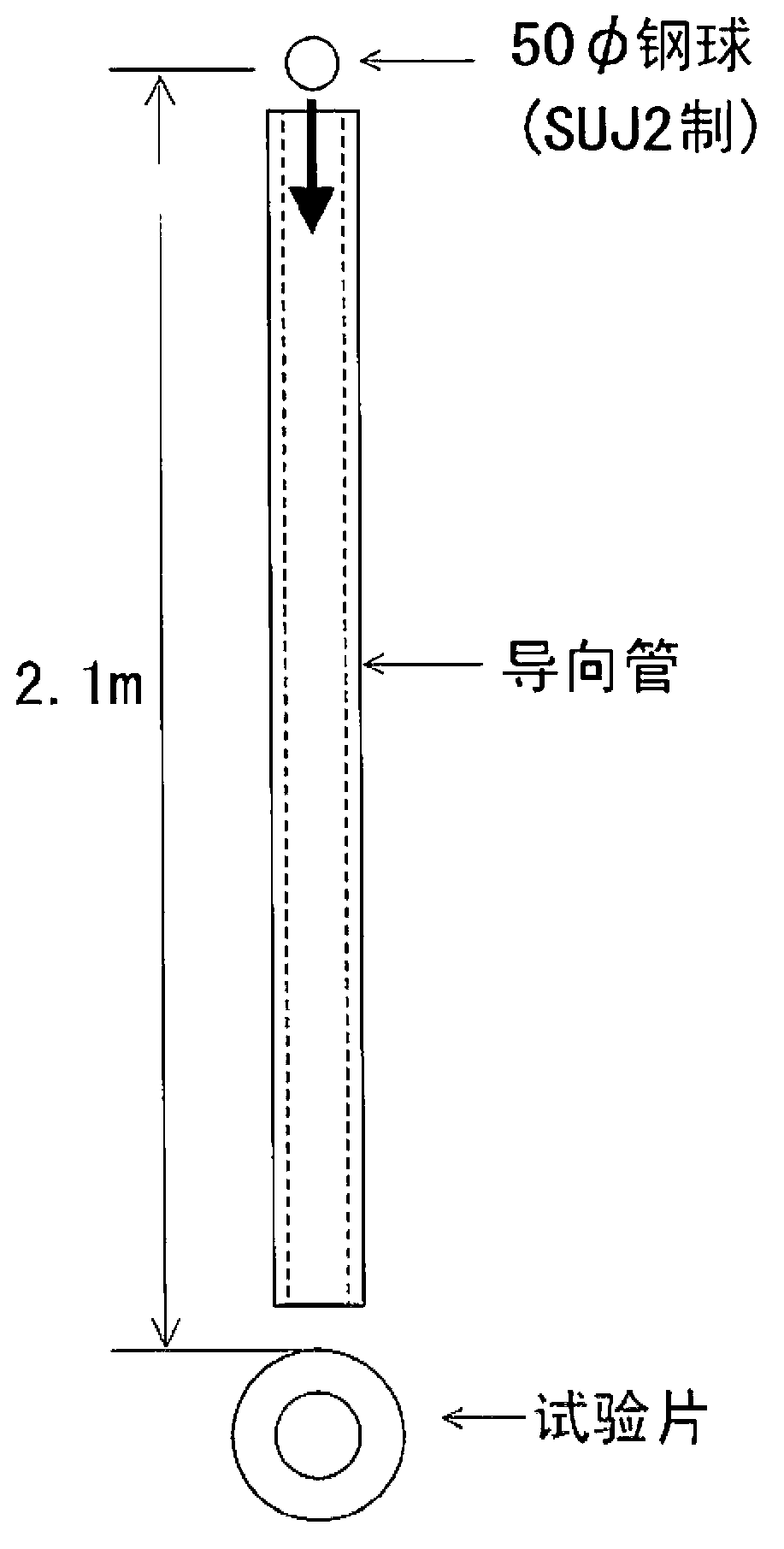
[0066] Using various steel materials with the composition shown in Table 1 with different Cr content and C equivalent Ceq the inside diameter of A ring-shaped test piece with a length of 100mm. Next, on the outer peripheral surface of the test piece, a Ni self-fluxing alloy mixed with 30% by mass of WC particles (WC-12Co sintered pulverized powder) with a particle size of 45 to 125 μm was sprayed using a powder flame spraying method to form a thickness of 3 mm. Self-fluxing alloy spray coating. However, for some test pieces, a hardfacing layer with a thickness of 10 mm was provided on the substrate before the self-fluxing alloy was sprayed, or a coating of only Ni self-fluxing alloy without WC particles was formed as a comparative example. Table 2 shows the self-fluxing alloys and hardfacing components used in the above coating formation.
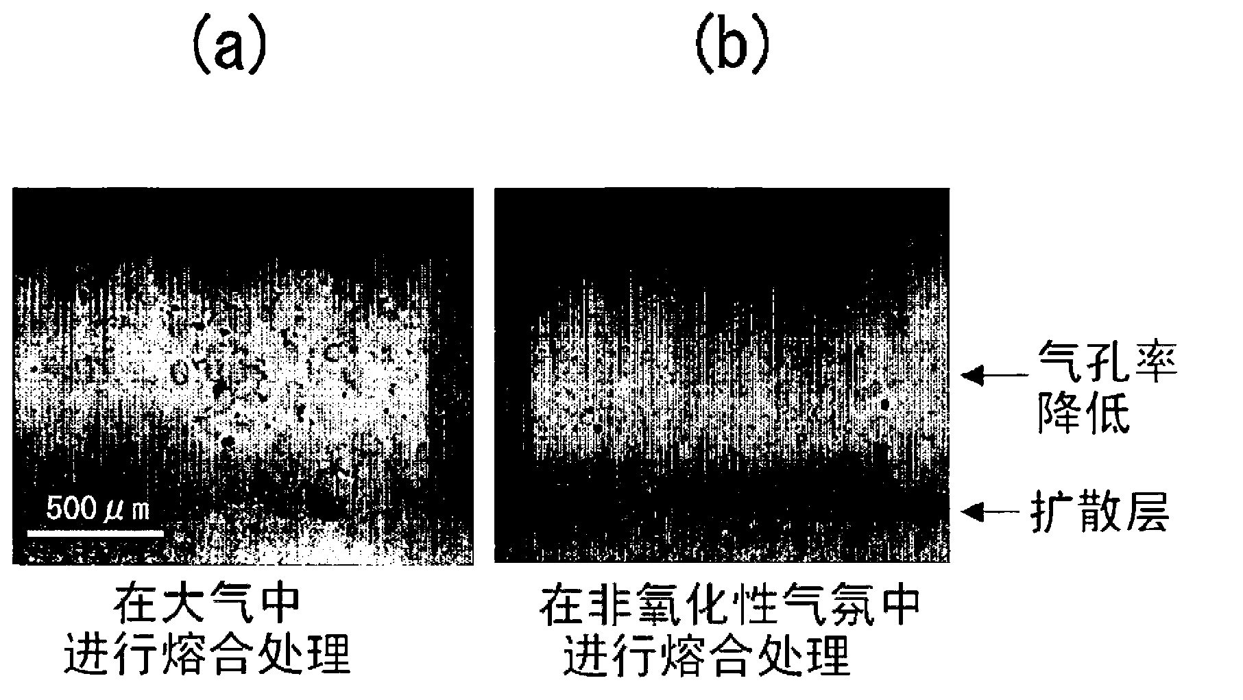
[0067] Next, the test piece after the thermal spray coating was formed was subjected to a fusion treatment at 1000°C for 60 minutes i...
Embodiment 2
[0087] Collect 20 mmt * 100 mm * 100 mm flat plates from various steel materials shown in Table 1, and in the thermal spraying conditions shown in Table 3 of Example 1, after cooling or heat treatment, the thermal sprayed coating was not confirmed under the condition of cracks. One surface of the flat plate is coated with a thermal spray coating, and after fusion treatment, cooling or heat treatment is performed. Next, use a #400 diamond grinding wheel to grind the surface of the sprayed coating, then cut and grind the side and non-sprayed surface to prepare a plate-shaped abrasion test piece of 5mmt×50mm×50mm, which is specified in JIS H8503 Suga abrasion test.
[0088] The above-mentioned abrasion test was performed under the condition of pressing SiC#320 abrasive paper with a load of 32N and reciprocating 2000 times, and the abrasion resistance was evaluated from the mass change (weight loss) of the test piece before and after the test. As a result, the abrasion resistance...
Embodiment 3
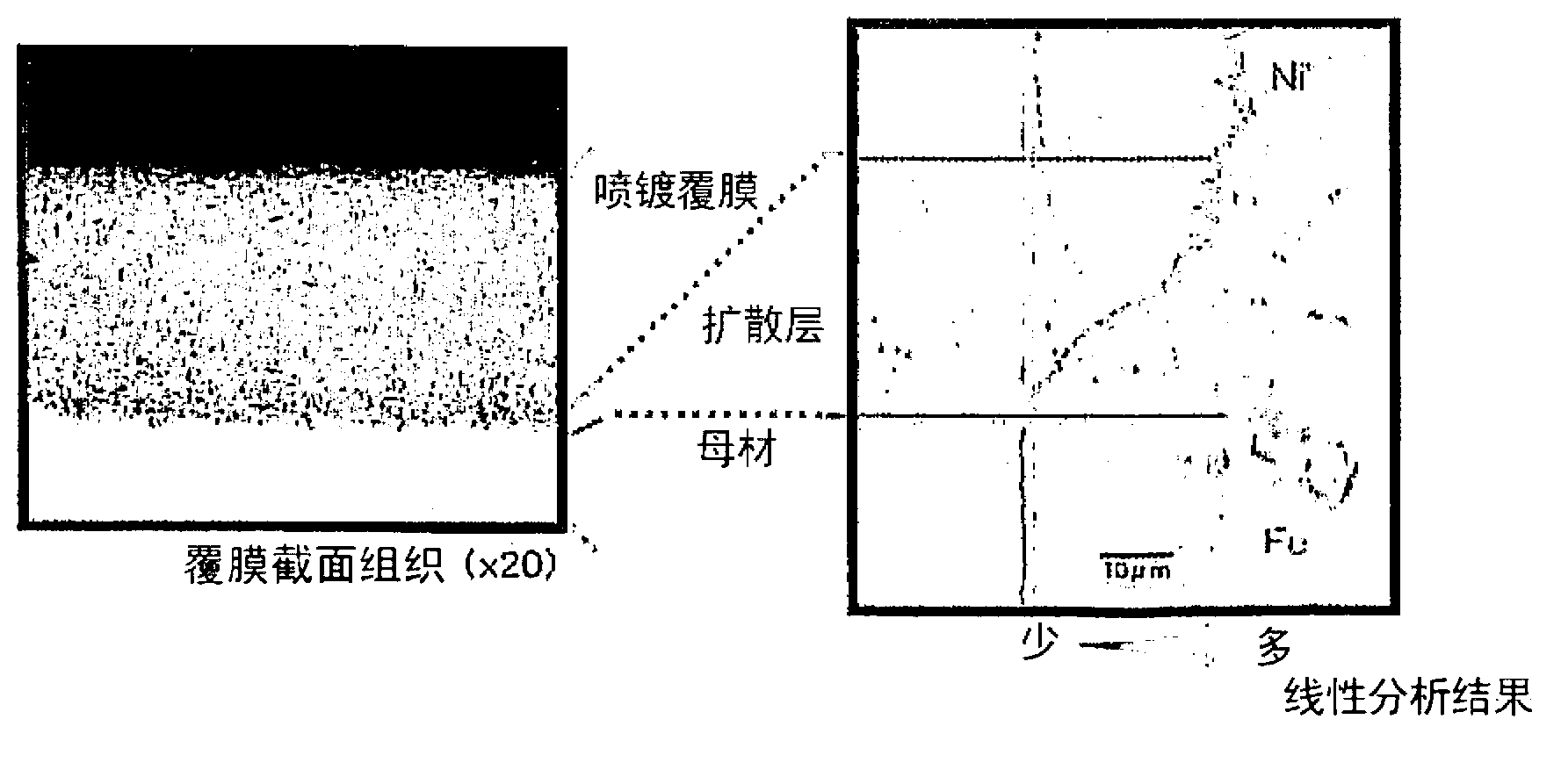
[0091] Under the same treatment conditions as No. 11, which showed good results in the falling ball test of Example 1 and the wear test of Example 2, for the steel using C shown in Table 1 (Cr: 1.3% by mass, Ceq: 1.25 mass%) as the outer diameter of the roll raw material The outer peripheral surface of the roller is sprayed with Ni self-fluxing alloy containing WC. After forming a 3mm thick sprayed coating, it is fused and then cooled, so that the Shore hardness HS of the roller substrate is 45. The roller substrate and the self-fluxing The thickness of the diffusion layer of the molten alloy is 30 μm for a roll for hot rolling equipment. As a result of applying this roll to the outer coiling roll of the hot rolling coiling facility in the ironworks, the sinking of the roll surface due to the entry of the front end of the steel plate and the accompanying peeling off of the sprayed coating were greatly reduced, which determine the life of the roll. The main limitation is th...
PUM
| Property | Measurement | Unit |
|---|---|---|
| Particle size | aaaaa | aaaaa |
| Thickness | aaaaa | aaaaa |
| Thickness | aaaaa | aaaaa |
Abstract
Description
Claims
Application Information
 - R&D
- Intellectual Property
- Life Sciences
- Materials
- Tech Scout
- Unparalleled Data Quality
- Higher Quality Content
- 60% Fewer Hallucinations
Browse by: Latest US Patents, China's latest patents, Technical Efficacy Thesaurus, Application Domain, Technology Topic, Popular Technical Reports.
© 2025 PatSnap. All rights reserved.Legal|Privacy policy|Modern Slavery Act Transparency Statement|Sitemap|About US| Contact US: help@patsnap.com


