Compressed-air storage device and natural energy power station with same

A gas storage device and compressed air technology, applied in fixed capacity gas storage tanks, gas/liquid distribution and storage, pressure vessels, etc., can solve problems such as inability to bear pressure, and achieve low cost, large volume, and high yield strength Effect

Active Publication Date: 2013-04-17
咸宁祥天空气能电力有限公司
View PDF7 Cites 2 Cited by
  • Summary
  • Abstract
  • Description
  • Claims
  • Application Information

AI Technical Summary

Problems solved by technology

At present, most pressure vessels are made of steel, and some are made of non-ferrous metals such as aluminum and titanium, and non-metallic materials such as glass fiber reinforced plastics and prestressed concrete. However, the strength of these materials cannot bear higher pressures, so It is necessary to further improve the material and structural design of the gas storage device

Method used


Image

  • Compressed-air storage device and natural energy power station with same
  • Compressed-air storage device and natural energy power station with same
  • Compressed-air storage device and natural energy power station with same

Examples


Embodiment 1

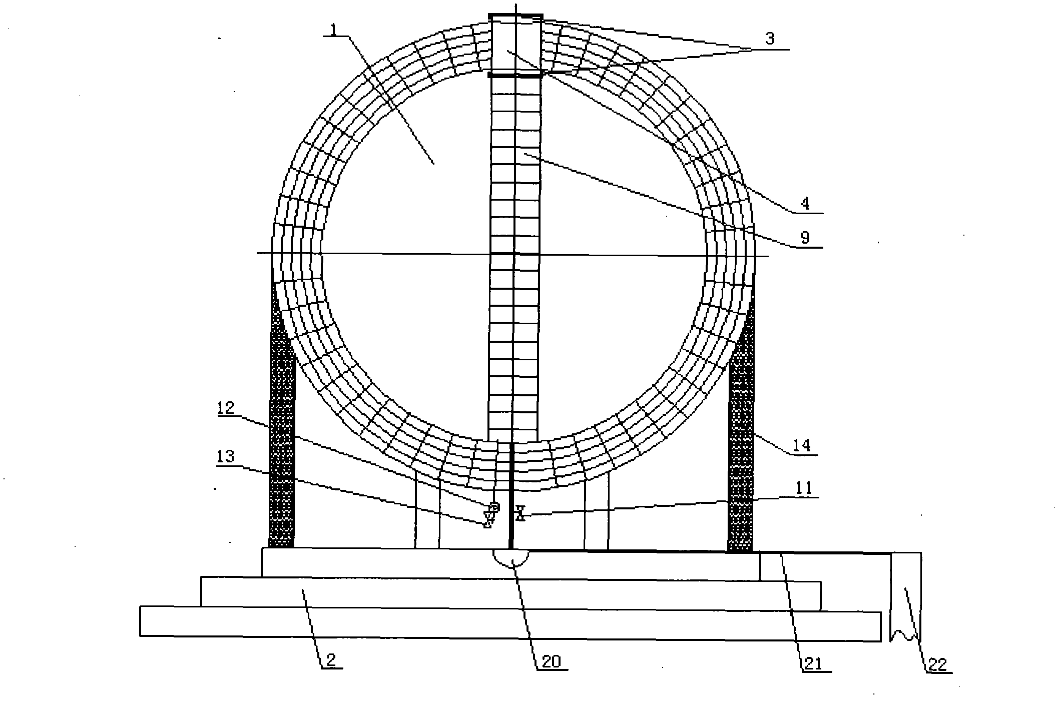
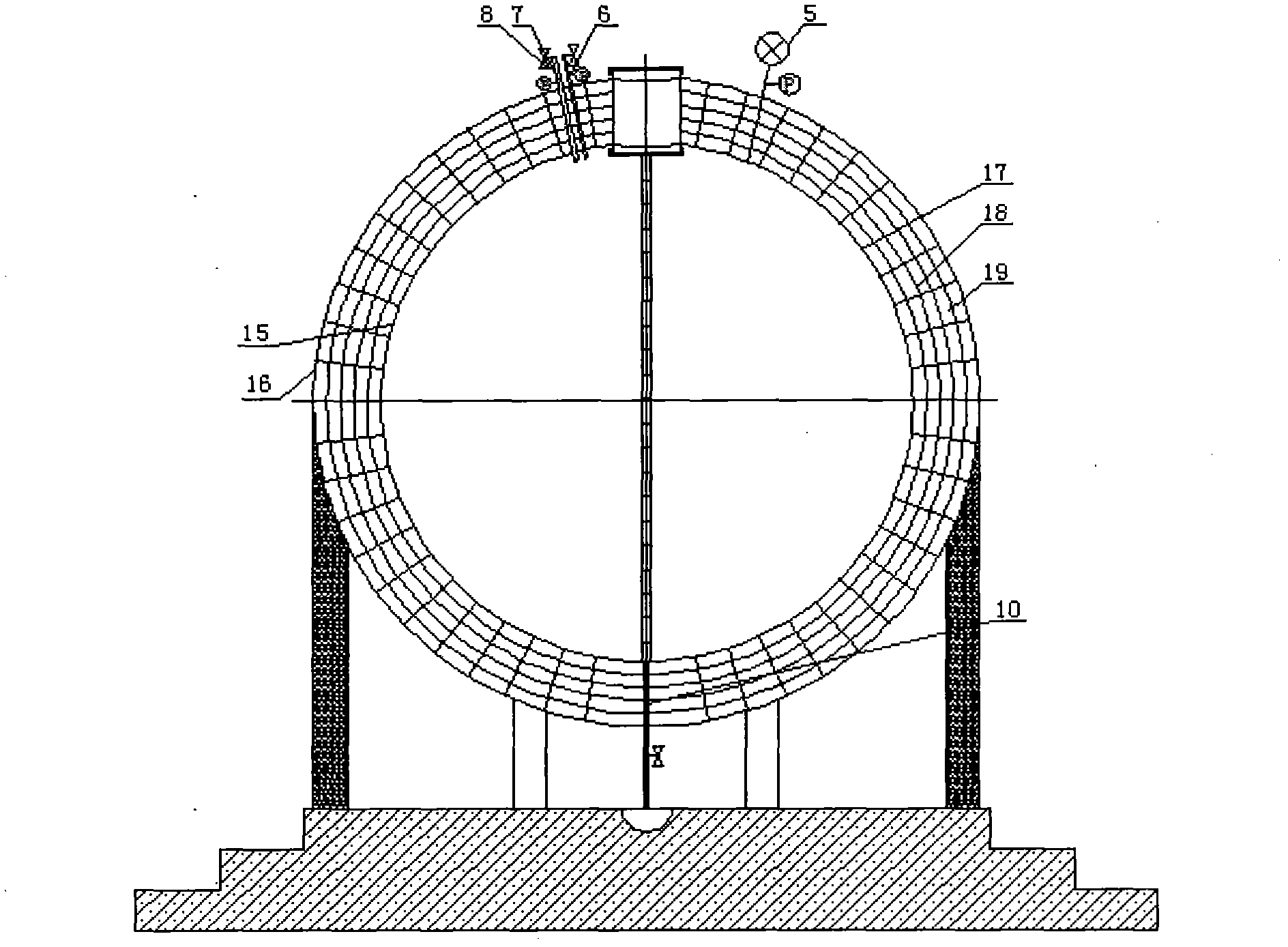
[0054] Such as figure 1 with figure 2 As shown, the decompression gas storage device of compressed air includes a spherical decompression gas storage tank 1, a sealing device and a drainage device. The decompression gas storage tank 1 is placed on six cement pillars 14, and the six cement pillars 14 are evenly distributed on the upper plane of the cement abutment 2, and the decompression gas storage tank 1 is lifted up so that the decompression gas storage tank 1 Smoother, eliminating vibration and noise.

[0055] The cement abutment 2 is a circular three-story staircase structure and is placed below the horizon. The upper plane of the cement abutment 2 is flush with the ground, and the radius of the upper plane is the smallest and larger than the radius of the pressure-reducing gas storage tank 1 . The installation method of placing the cement abutment 2 below the horizon can make the placement of the pressure-reducing air storage tank 1 more stable with less vibration. T...

Embodiment 2

[0064] The depressurization gas storage device for compressed air, the positional relationship and connection relationship between each component, and the natural energy power station equipped with this device are the same as the first embodiment.

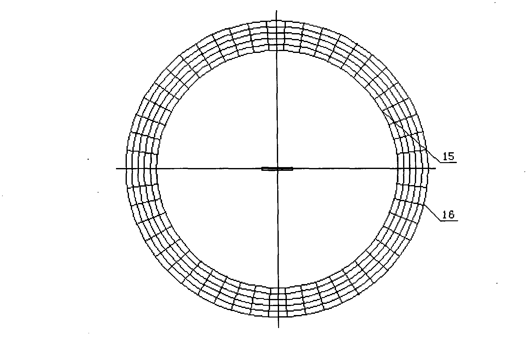
[0065] Such as image 3 with Figure 4 As shown, the material of the shell inner wall 15 and the shell outer wall 16 of the step-down gas storage tank 1 is ship plate steel with a yield strength of 820MPa and a thickness of 7mm. Ship plate steel has high yield strength, high low temperature impact toughness, good welding performance and cold bending resistance. The volume of step-down gas storage tank 1 is 1022m 3 , capable of carrying a pressure of 1550 atmospheres.

Embodiment 3

[0067] The depressurization gas storage device for compressed air, the positional relationship and connection relationship between each component, and the natural energy power station equipped with this device are the same as the first and second embodiments.

[0068] Such as image 3 with Figure 4 As shown, the material of the shell inner wall 15 and the shell outer wall 16 of the decompression gas storage tank 1 is ship plate steel with a yield strength of 1000 MPa and a thickness of 10 mm. Ship plate steel has high yield strength, high low temperature impact toughness, good welding performance and cold bending resistance. The volume of step-down gas storage tank 1 is 1022m 3 , capable of carrying a pressure of 1800 atmospheres.


PUM


Abstract

The invention relates to a compressed-air storage device and a natural energy power station with the compressed-air storage device. The compressed-air storage device comprises an air storage tank, a sealing device and a water draining device. The air storage tank is arranged on six cement columns which are uniformly distributed and support the air storage tank; the cement columns are placed on the upper plane of a cement base station; the top of the air storage tank is connected with the sealing device, while the bottom of the air storage tank is provided with the water draining device; and ladders are arranged between the water draining device and the sealing device and uniformly distributed on a shell of the air storage tank. Both the inner wall and the outer wall of the air storage tank are made from ship plate steel with yield strength being 550-1,000 MPa and thickness being 5-10 mm. The shell of the air storage tank is 1m in thickness and 1,022 m<3> in capacity and can bear 1,200-1,800 atmospheres. The natural energy power station is provided with the compressed-air storage device. The technical solution generates the following benefits that the air storage device is simple in structure and the material of the air storage tank has high the yield strength and can bear large pressure.

Description

technical field [0001] The invention relates to a gas storage device, in particular to a compressed air gas storage device and a natural energy power station equipped with the device. Background technique [0002] Since the development of society, human's demand for energy has increased substantially every year. As fossil fuels such as coal, oil, and natural gas become less and less, environmental problems such as air pollution, water depletion, and global warming are becoming more and more serious. Therefore, it is of great practical significance to develop and utilize new, pollution-free, and renewable clean energy. Coal, oil, natural gas and other fuels for power generation will produce a large amount of greenhouse gases, and nuclear power generation will face the problem of nuclear waste disposal. They are not conducive to environmental protection, while wind energy and solar energy are inexhaustible pollution-free renewable energy. Therefore, the power generation syste...

Claims


Application Information

Patent Timeline
Patent Type & Authority Applications(China)
IPC IPC(8): F17C1/00F17C13/00
Inventor 周登荣周剑
Owner 咸宁祥天空气能电力有限公司
Why Eureka
Try Eureka