Spiral vibrating bed waste heat recovery device in melted blast furnace slag granulation process

A technology of waste heat recovery device and granulation process, which is applied in the direction of recycling technology, furnace, furnace components, etc., can solve the problems of increasing cooling air volume, increasing equipment size, and insufficient cooling speed, so as to extend the flow distance and reduce the Dimensions, effect of preventing sticking

Inactive Publication Date: 2013-04-24
UNIV OF SCI & TECH BEIJING
View PDF5 Cites 11 Cited by
  • Summary
  • Abstract
  • Description
  • Claims
  • Application Information

AI Technical Summary

Problems solved by technology

[0006] In order to achieve the purpose of rapid cooling of molten blast furnace slag, and to solve the problems of insufficient cooling speed or slag particles sticking to the wall during the dry granulation process of molten blast furnace slag, the previous method was to increase the size of the equipment and increase th

Method used


Image

  • Spiral vibrating bed waste heat recovery device in melted blast furnace slag granulation process
  • Spiral vibrating bed waste heat recovery device in melted blast furnace slag granulation process
  • Spiral vibrating bed waste heat recovery device in melted blast furnace slag granulation process

Examples


specific Embodiment approach 1

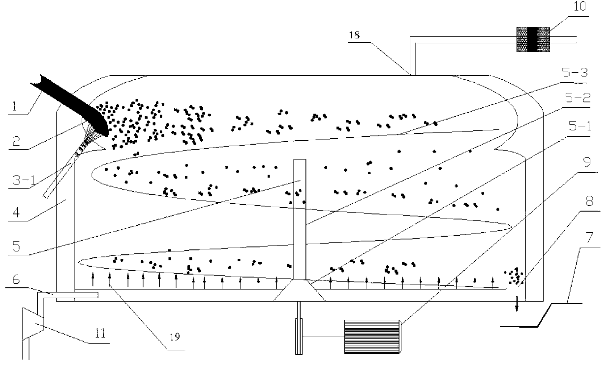
[0031] Specific implementation mode one: for the air quenching granulation treatment method, the attached figure 2As shown in the structural device, the molten slag 2 discharged from the blast furnace at about 1500°C enters the granulation chamber shell 4 of the granulation device through the draft pipe 1, and is broken into molten slag by the high-pressure gas stream injected from the nozzle 3-1. Slag particles, the slag particles pass through the spiral vibrating bed 5 during flight and landing, and are cooled by the cooling air at the bottom through the air pipe 6 to rapidly cool and prevent sticking. The particle outlet 8 flows to the slag particle conveying device 7 and is transported to the secondary cooling chamber 14; the high-temperature air after heat exchange is sprayed out through the high-temperature air outlet 18, and after being dedusted by the first dust collector 10, part of it is transported to the hot blast stove In 13, the other part is slowly transported ...

specific Embodiment approach 2

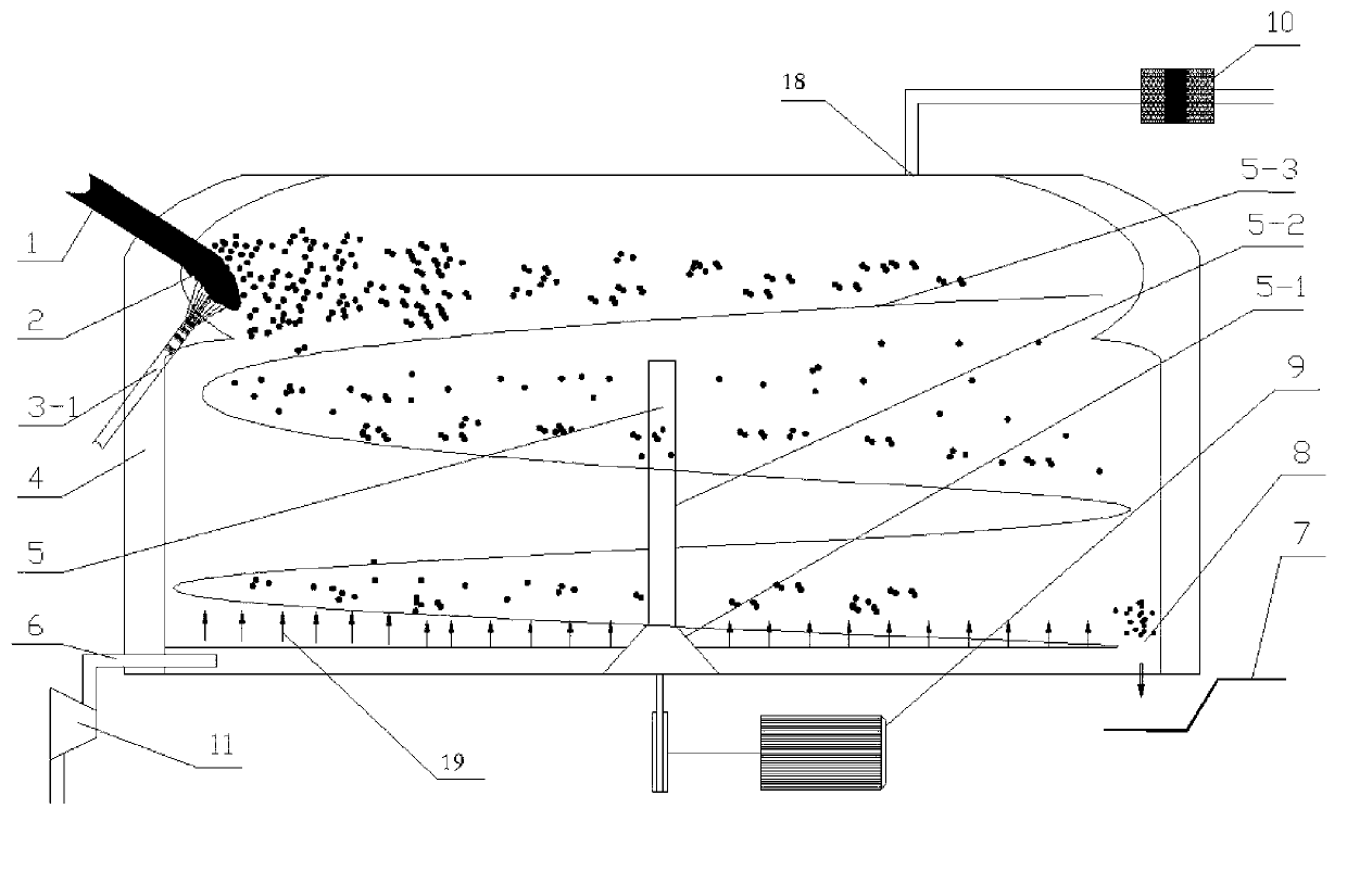
[0032] Specific implementation mode two: for the centrifugal granulation treatment method, adopt the attached image 3 As shown in the structural device, the molten slag 2 discharged from the blast furnace at about 1500°C enters the granulation device through the draft pipe 1, and is granulated and broken into molten slag particles by the centrifugal granulation device 3-2. The slag particles are flying and falling Through the spiral vibrating bed 5, through the bottom cooling, the cooling air passed through the air pipe 6 is rapidly cooled and prevented from sticking, and when the temperature of the slag particles drops to 850°C~1000°C, it flows to the slag particle conveying device 7 through the slag particle outlet 8 Transported to the secondary cooling chamber 14; the high-temperature air after heat exchange is sprayed out through the high-temperature air outlet 18, and after being dedusted by the first dust collector 10, part of it is transported to the hot blast stove 13,...


PUM


Abstract

The invention discloses a spiral vibrating bed waste heat recovery device in a melted blast furnace slag granulation process. The device consists of a spiral vibrating bed rapid cooling unit in a granulation stage and a waste heat recovery unit. The spiral structure of the spiral vibrating bed rapid cooling unit in the granulation stage can prolong landing distances of melted blast furnace slag particles after the melted blast furnace slag particles are subjected to dry-method granulation process, bottom circulating cooling air and the melted slag particles are subjected to heat exchange through pores on a screening bed surface in a countercurrent way, so that the cooling speed is improved, a target of quenching the blast furnace slag is realized, the bonding between the melted slag particles and between the slag particles and a vibrating bed surface is effectively prevented, and the blast furnace slag particles with glass structures are obtained as many as possible; and the waste heat recovery unit comprises a matched dedusting and air supply system, a secondary cooling device and a waste heat utilization device. High-temperature air recovered by the spiral vibrating bed rapid cooling unit in the granulation stage is provided for a hot air furnace through a dust remover and an air supply pipeline part, the rest of high-temperature air is fed into the secondary cooling device for continuous heat exchange and heating up, and the high-temperature air at a temperature of 700 DEG C enters a waste heat boiler for generating steam for power generation.

Description

technical field [0001] The invention belongs to the technical field of high-temperature solid waste treatment and recovery of waste heat and energy, and in particular relates to a spiral vibrating bed waste heat recovery device for molten blast furnace slag in the solidification and cooling process in the dry granulation treatment of molten blast furnace slag liquid. Background technique [0002] The metallurgical industry is the largest energy-consuming unit, with an annual energy consumption of 20GJ. Since 1980, my country's iron and steel industry has made great achievements in energy saving, but there is still a shortage in the recycling of waste heat resources. Relevant research results show that the sensible heat recovery rates of flue gas, cooling water and molten slag are very low. Among them, the recovery rate of slag sensible heat is the least, only 1.59%. Iron and steel industry slag includes ironmaking blast furnace slag, steelmaking slag, ferroalloy slag, no...

Claims


Application Information

Patent Timeline
IPC IPC(8): C21B3/06C21B3/08F27D17/00
CPCC21B2400/026C21B2400/034C21B2400/07C21B2400/08Y02P10/20Y02P10/25Y02W30/50
Inventor 冯俊小陈艳梅
Owner UNIV OF SCI & TECH BEIJING
Why Eureka
Try Eureka